Replacing a mechanical seal on a
water pump is one of the most common maintenance tasks in industrial and commercial
water systems — and one of the most frequently done incorrectly. A failed seal is also
one of the most misdiagnosed problems: what appears to be a seal failure is often a
symptom of a shaft alignment problem, a cavitation issue, or running the pump dry.
Fitting a new seal without addressing the root cause means the replacement seal will
fail for the same reason, often within days. This guide covers not just how to
replace the seal, but why it failed, what to check before installing the new
one, and how to commission the pump correctly afterwards so the seal beds in and lasts
its full-service life. Note that mechanical seals are used across many pump types — in a
gear pump, for example, the seal
design and replacement procedure differs from a centrifugal water pump, which this guide
focuses on specifically.
Know More: How to
Measure a Mechanical Seal
Before You Replace Anything: Diagnose Why the Seal Failed
The most important step in mechanical seal replacement is not the replacement itself — it
is understanding what caused the seal to fail. Mechanical seals in water pumps,
correctly installed and operated, routinely last 2–5 years or longer. If your seal
failed early, something in the operating conditions caused it. Replacing the seal
without identifying that cause is the most common reason maintenance teams find
themselves replacing the same seal again within weeks.
Examine the Old Seal Before Discarding It
The condition of the removed seal faces tells you the failure mode:
| What You See on the Old Seal |
What It Means |
What to Fix Before Installing New Seal |
| Uniform wear across both seal faces — fine wear track visible |
Normal end-of-life wear — seal lasted its service life |
No corrective action needed; check shaft runout as a precaution |
| Cracked or chipped seal face (ceramic or carbon) |
Dry running — pump ran without fluid, seal faces overheated |
Investigate why pump ran dry: check inlet valve, suction line, controls
|
| Heavy scoring or scratching across face |
Particulate contamination in the fluid |
Fit a suction strainer; consider an upgraded hard face material (SiC vs
SiC) |
| Coking or burnt residue on faces and spring |
Overheating — inadequate fluid film, excessive shaft speed, or wrong
seal for the temperature |
Check pump operating speed; verify seal type matches fluid temperature
|
| Uneven or partial wear track (crescent shape on face) |
Shaft misalignment or excessive runout |
Measure and correct shaft alignment before new seal installation |
| Swollen, hardened, or cracked O-rings / elastomers |
Chemical incompatibility between fluid and seal elastomer material |
Select replacement seal with correct elastomer for the fluid (Viton,
EPDM, PTFE) |
| Corroded metal components (spring, drive collar) |
Wrong metal grade for the water chemistry (e.g., chlorinated or acidic
water) |
Specify correct metal grade — 316 SS for most water applications |
| Fretting wear on shaft sleeve under the seal |
Seal was loose on shaft — set screws undertorqued or wrong bore size
|
Clean shaft, check bore diameter against seal spec, torque set screws
correctly |
Rule of thumb: Never install a new mechanical seal without examining the old one
first. The faces, O-rings, and metal components each tell a different story. A
5-minute inspection before the new seal goes in is worth more than any number of
seal replacements after the fact.
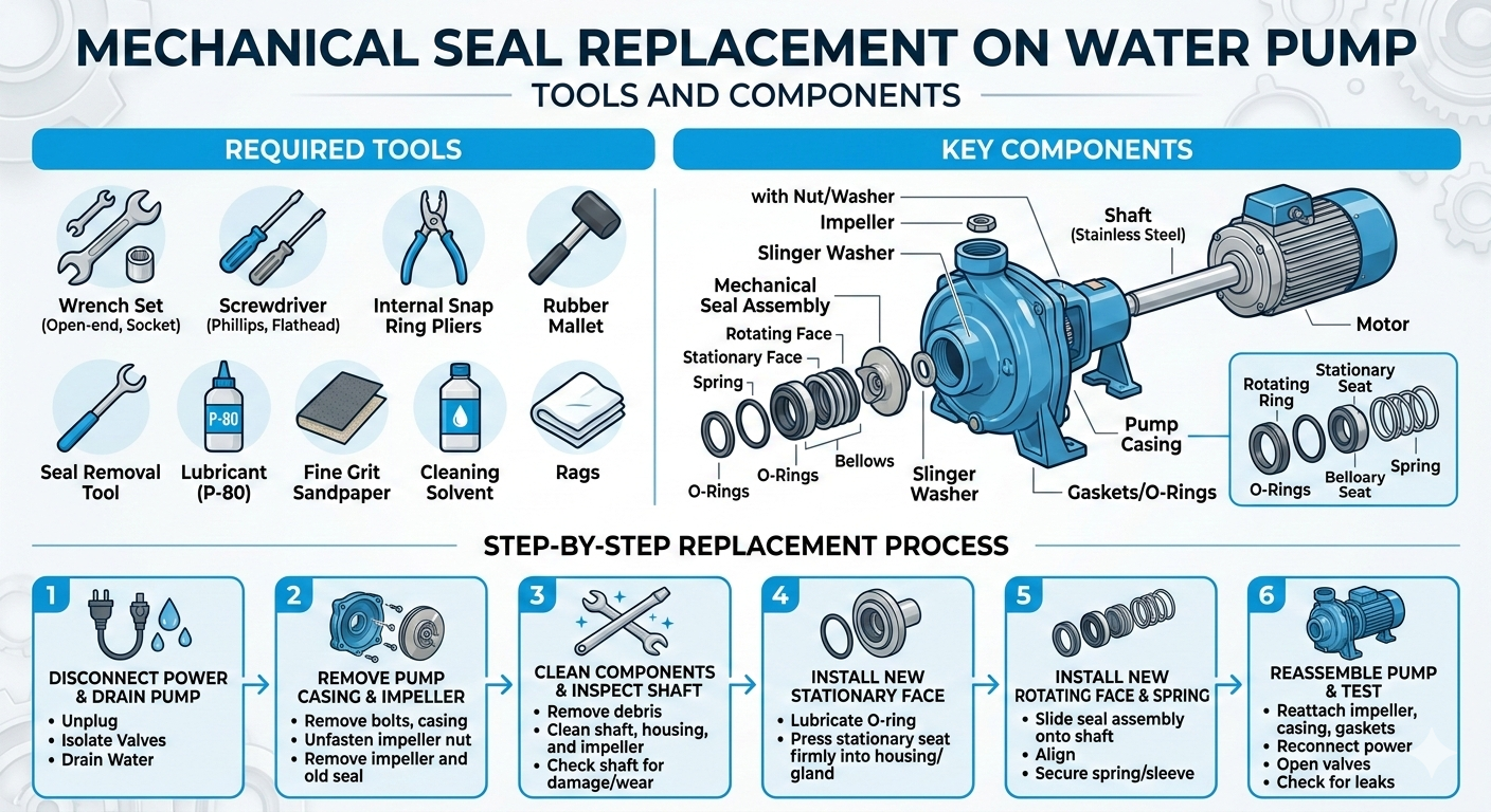
Tools and Materials You Need Before Starting
Attempting a seal replacement without the right tools is the second most common cause of
installation failure. Improvised tools — screwdrivers used as chisels, pliers used to
press seal faces — damage the precision lapped surfaces that make mechanical seals work.
Assemble everything before the pump is opened.
Tools
Materials
- Replacement mechanical seal — correct type, bore size, and elastomer for the
application
- Replacement O-rings and gaskets — do not reuse old elastomers even if they
appear intact
- Isopropyl alcohol (IPA) — for cleaning seal faces, shaft, and seal chamber
(never use mineral spirits on seal faces)
- Light machine oil or soapy water — for lubricating O-rings during installation
(use only what is compatible with the seal elastomer)
- Anti-seize compound — for threads on impeller bolt/nut if corrosion is present
- Thread-locking compound — for set screws if specified by the seal manufacturer
⚠ Never use petroleum-based lubricants (grease, WD-40, mineral oil) to lubricate
EPDM O-rings — petroleum swells EPDM. Use soapy water or glycerin instead. For NBR
and Viton O-rings, light machine oil is acceptable.
Know Your Pump Configuration Before You Start Disassembly
Water pumps come in several configurations, and the disassembly sequence and seal access
route is different for each. Starting to disassemble without knowing which type you have
is how couplings get damaged and casings get cracked.
| Pump Configuration |
How to Identify It |
Seal Access Method |
| Back Pull-Out (most common in industrial service) |
Motor and pump share a baseplate; pump casing stays connected to
pipework; the back plate, shaft, and impeller pull away as an assembly
|
Remove coupling spacer element → remove casing bolts → slide back
pull-out assembly rearward → seal is accessible without disturbing
pipework |
| Close-Coupled (motor shaft IS the pump shaft) |
Pump casing bolts directly onto motor face; no separate coupling |
Disconnect pipework → remove entire pump/motor assembly → remove casing
→ remove impeller → seal accessible |
| Frame-Mounted (separate pump and motor, rigid coupling)
|
Pump and motor on baseplate, connected by a rigid or flexible coupling
|
Disconnect coupling → remove pump from baseplate (if needed) → remove
casing → remove impeller → seal accessible |
| Inline / Pipeline pump |
Pump body installed directly in the pipeline, no separate baseplate |
Isolate and drain section of pipe → remove pump body from pipework
flanges → disassemble casing → remove impeller → seal accessible |
| Submersible pump |
Motor and pump both submerged — shaft seal prevents water entering motor
|
Retrieve pump from sump → disassemble motor/pump interface → seal is at
the shaft penetration between pump and motor sections |
This guide follows the back pull-out sequence as it is the most common configuration in
industrial water pump service and the sequence the competitor's guide also follows — but
with important differences in the inspection steps and commissioning procedure covered
below.
Step-by-Step: How to Replace a Mechanical Seal on a Water Pump
1 Isolate All Energy Sources
Mechanical seal replacement requires full energy isolation — not just switching off the
pump. A pump that restarts unexpectedly during seal replacement can cause serious
injury.
- Switch off the pump motor at the isolator (not just the control panel)
- Lock out and tag out (LOTO) the electrical isolator — physically lock it in the OFF
position
- Close the suction isolation valve
- Close the discharge isolation valve
- If the pump handles hot water (above 40°C), allow it to cool to a safe working
temperature before opening any part of the pump
⚠ Do not rely on a motor stop button alone. If there is any possibility of
back-pressure from the discharge side restarting flow through the pump, both valves
must be closed and confirmed shut before any part of the pump is opened.
2 Drain the Pump and Record Reference Measurements
Before disassembly, take a few measurements that will be needed during reassembly:
- Open the casing drain plug and drain all fluid from the pump casing — place a
suitable container beneath
- Measure and record the distance from the coupling hub face to the shaft end (this is
your reference for shaft axial position after reassembly)
- If the pump has a seal flush connection or lantern ring, note its configuration and
photograph it before disconnecting
- Photograph the pump from the seal end before disassembly — reference photos are
invaluable if there is any uncertainty during reassembly
3 Remove the Coupling Spacer (Back Pull-Out Design)
For back pull-out designs, the coupling spacer element between pump coupling hub and
motor coupling hub is removed first. This is what allows the back pull-out assembly to
be withdrawn without moving the motor.
- Loosen and remove the coupling guard
- Remove the coupling spacer element — typically secured by bolts or clamps depending
on the coupling type
- Do not disturb the coupling hubs on either the pump shaft or motor shaft at this
stage
✓ If this is the first time the pump has been serviced, photograph the coupling
alignment marks and check whether alignment was correctly set at commissioning.
Misalignment is a primary cause of early seal failure — if the pump was never
correctly aligned, the new seal will fail for the same reason.
4 Remove the Casing Bolts and Withdraw the Back
Pull-Out Assembly
- Remove the casing bolts in a cross-pattern (alternating diagonally opposite bolts) —
this releases casing pressure evenly and prevents the casing from tilting and
damaging the casing wear rings
- Support the weight of the back pull-out assembly before the last bolts come out — do
not let it drop
- Slide the back pull-out assembly (comprising the bearing housing, shaft, impeller,
and seal) rearward away from the casing — the casing and its pipework connections
remain in place
- Place the back pull-out assembly on a clean work surface
5 Remove the Impeller
The mechanical seal sits behind the impeller on the shaft. The impeller must come off
before the seal is accessible.
- Screwed impeller: Hold the shaft firmly with a strap wrench or by inserting a bar
through the coupling hub (never grip the shaft surface with metal tools — this
creates runout-inducing marks). Rotate the impeller clockwise (standard right-hand
thread) to unscrew it. Some impellers on pumps that reverse direction may have
left-hand threads — check the manufacturer's documentation.
- Bolted impeller: Hold the shaft and remove the central impeller bolt. The impeller
may be a taper fit — a gentle tap with a soft mallet on the impeller hub (not the
vanes) will free it if it does not slide off.
- Once removed, inspect the impeller for wear, erosion, and any imbalance damage — a
visibly damaged impeller will cause vibration that will shorten the new seal's life
even after correct installation
⚠ Never use heat to free a stuck impeller from a shaft with a mechanical seal
already in place — the heat will destroy the seal faces and O-rings. If the impeller
is seized, apply penetrating fluid to the shaft/impeller interface and allow time to
work before trying again.
6 Remove the Old Mechanical Seal
With the impeller removed, both the rotating assembly (on the shaft) and the stationary
seat (in the seal chamber or gland plate) are now accessible.
- Rotating assembly: Locate the set screws in the drive collar or spring holder —
these are what lock the rotating portion to the shaft. Loosen each set screw fully
(do not just back them off — fully remove if they will interfere with sliding).
Slide the entire rotating assembly (spring, drive collar, rotating face) off the
shaft toward the impeller end.
- Stationary seat: The stationary seat sits in a recess in the seal chamber bore or
gland plate, retained by an O-ring interference fit. Use a wooden or plastic dowel
to push it out from behind — never use a metal screwdriver directly against the seat
face. If it is particularly tight, a rubber-tipped puller rod helps.
- Inspect both removed components as described in Section 1 before proceeding
7 Inspect and Prepare the Shaft and Seal Chamber
This is the step most rushed in field maintenance — and the one where the majority of
premature new seal failures originate. Take as long as needed here.
- Check shaft runout: Mount a dial indicator on a magnetic base and measure radial
runout at the shaft surface in the seal area. Rotate the shaft by hand through one
full revolution. Maximum acceptable runout for most mechanical seals is 0.05 mm
(0.002") TIR (Total Indicator Reading). Runout above this will cause the rotating
face to wobble relative to the stationary seat, preventing a stable fluid film and
causing rapid face wear.
- Check shaft diameter: Measure the shaft with a micrometer at the seal location.
Compare to the seal manufacturer's bore specification. The shaft should be at the
correct diameter within tolerance — a shaft worn undersize will not hold the O-ring
on the rotating assembly correctly, allowing micro-movement that causes leakage and
fretting.
- Inspect shaft surface finish: The shaft surface under the O-ring and set screw area
must be smooth and free from corrosion pits, score marks, or rust. Light corrosion
can be polished with fine emery cloth (400–600 grit) followed by IPA cleaning. Heavy
corrosion, deep pitting, or score marks indicate the shaft sleeve needs replacement.
- Clean the seal chamber bore: Wipe the seal chamber bore with a clean lint-free cloth
dampened with IPA. Any debris, old O-ring material, or corrosion in the bore will
prevent the stationary seat from seating squarely — causing it to run tilted
relative to the rotating face.
- Check the gland plate face: The face of the gland plate (where it contacts the pump
casing) must be clean and undamaged. A damaged or corroded gland face prevents the
gland from seating flat, which can tilt the stationary seat and compromise face
alignment.
Shaft runout is the single most overlooked cause of early seal failure in water pump
maintenance. A bent shaft, worn bearing, or misaligned coupling will cause runout
that no mechanical seal can compensate for. If runout exceeds 0.05 mm, fix the
shaft/bearing/alignment issue before installing the new seal.
8 Install the New Stationary Seat
The stationary seat is the more fragile of the two seal components and the more
frequently damaged during installation.
- Remove the new stationary seat from its packaging — hold it only by the sides, never
touch the lapped face with bare fingers (body oils contaminate the face and create
high spots that prevent a flat fluid film from forming)
- Lightly lubricate the O-ring on the outside of the stationary seat with a drop of
soapy water or IPA-dampened cloth — just enough to ease installation, not so much
that it slides freely before seating
- Align the seat with any anti-rotation slot or pin in the seal chamber bore — this
prevents the stationary seat from rotating with the shaft
- Using a clean seal installation sleeve (or a piece of clean tubing with a square-cut
end that matches the seat diameter), press the stationary seat squarely into the
bore with steady, even hand pressure
- Confirm the seat is fully and evenly seated — it should be flush with or just below
the bore face, with no tilting or rocking
⚠ Never use metal tools to tap the stationary seat into the bore. A single
impact on the ceramic or silicon carbide face will create an invisible microcrack
that causes the face to fail within hours of starting the pump.
9 Install the Rotating Assembly
The rotating assembly (comprising the spring, drive collar, and rotating face) slides
onto the shaft from the impeller end.
- Wipe the shaft surface in the seal area one final time with a clean IPA-dampened
cloth
- For cartridge seals: slide the entire pre-assembled cartridge onto the shaft as a
unit — do not disassemble a cartridge seal. The cartridge clips or gauging clips
that hold it at the correct spring compression must remain in place until after the
impeller is reinstalled and the gland is bolted
- For component seals: lightly lubricate the rotating assembly O-ring and slide the
rotating face holder onto the shaft, followed by the spring, and then the drive
collar — in the sequence specified by the seal manufacturer's drawing
- Verify the spring compression length: measure the distance from the rotating face to
the drive collar set screw position and confirm it matches the seal manufacturer's
'working length' specification. Incorrect spring compression is a common cause of
seal failure — too little compression means the faces do not stay in contact; too
much means excessive face load, rapid wear, and heat generation
- Tighten the set screws to the manufacturer's specified torque using a calibrated hex
key or torque screwdriver. Do not guess. Undertorqued set screws allow the rotating
assembly to move axially on the shaft; overtorqued set screws score the shaft and
cause runout
✓ For component mechanical seals with multiple set screws, tighten them in a star
pattern (not sequentially around the collar) to ensure even clamping force and
prevent the drive collar from seating at an angle on the shaft.
10 Reinstall the Impeller
- Screwed impeller: Use a new impeller O-ring or gasket — never reuse the old one.
Lubricate the O-ring lightly. Hold the shaft and thread the impeller onto the shaft,
then tighten to the torque value specified in the pump IOM.
- Bolted impeller: Fit the impeller onto the taper or key, then install the impeller
bolt with a new locking washer or thread-locking compound as specified. Torque to
specification.
- Confirm that the impeller does not contact the casing wear rings by turning it by
hand with the shaft — it should rotate freely with uniform clearance
11 Reassemble the Pump Casing
- For cartridge seals: remove the cartridge gauging clips NOW — before the casing is
reassembled. These clips hold the spring compressed for installation; leaving them
in place means the seal faces will not be in contact when the pump runs
- Clean the casing joint face and install a new casing gasket or O-ring (do not reuse
the old one)
- Slide the back pull-out assembly back into the casing, taking care not to damage the
impeller vane tips against the casing volute
- Install the casing bolts and tighten in a cross-pattern to the torque specified in
the pump IOM — uneven torque on the casing bolts causes the casing to deform and can
misalign the seal chamber
12 Reinstall the Coupling and Check Alignment
- Reinstall the coupling spacer element
- Check pump-to-motor alignment before reconnecting the coupling — this is mandatory
even if nothing has changed, because removing and reinstalling the back pull-out
assembly can shift the pump's position on the baseplate
- Acceptable alignment is: parallel misalignment less than 0.05 mm and angular
misalignment less than 0.05 mm per 100 mm of coupling diameter (refer to coupling
manufacturer's specification for the exact allowable values for your coupling type)
- Reinstall the coupling guard
⚠ Misalignment is the number one cause of premature mechanical seal failure in
water pumps. The time spent checking and correcting alignment after every seal
replacement is not optional — it is the most effective seal life extension measure
available. A pump running with 0.2 mm misalignment will destroy a new mechanical
seal in days or weeks.
Post-Installation Commissioning — Do Not Skip These Steps
The seal is installed. The pump is reassembled. But the job is not finished until the
pump has been correctly commissioned and the new seal has been confirmed to be bedding
in correctly. This section is entirely absent from most seal replacement guides —
including the competitor's — and it is where many otherwise correct installations go
wrong.
Vent the Pump Casing Before Starting
Air trapped in the pump casing at startup causes dry running of the mechanical seal for
the first few seconds — which is enough to crack a ceramic or carbon face. Before
starting the pump:
- Open the suction isolation valve fully
- Open the vent plug or highest point of the casing (if fitted) until fluid flows
steadily — confirming the casing is full and air-free
- Close the vent plug
- Open the discharge isolation valve to the normal operating position
Many water pump seals fail on their first start because the casing was not vented.
The seal ran dry for 5–10 seconds while the casing filled. This is enough to crack a
ceramic seat. Always vent before starting.
Bump Test Motor Rotation Direction
Before fully coupling the pump and motor, bump (briefly energise and immediately
de-energise) the motor alone to confirm its rotation direction matches the pump's
required rotation direction. An impeller running in the wrong direction produces no flow
and creates violent pressure fluctuations that instantly overload the mechanical seal.
- Disconnect the coupling before the bump test if it is already connected
- Energise the motor for 1–2 seconds and observe rotation direction from the non-drive
end
- Compare to the rotation direction arrow on the pump casing or IOM
- If rotation is wrong, swap any two phases of the motor supply (requires a qualified
electrician)
Initial Start and Seal Bedding-In Period
New mechanical seal faces — even precision-lapped ones — have microscopic surface
irregularities that settle and smooth out during the first few hours of operation. This
is the bedding-in period, and how the pump is operated during this time determines
whether the seal reaches its full service life or fails prematurely.
- Start the pump and immediately check for leaks at the gland plate face (stationary
seat area) and from around the shaft
- Observe the seal area for the first 5 minutes — a small amount of fluid weeping from
the seal area in the first few minutes of operation is normal and indicates the
faces are lubricating correctly. This should reduce to vapour-only within 15–30
minutes
- If sustained dripping continues beyond 30 minutes of operation, shut down and
investigate — do not continue running
- Avoid running the pump at maximum speed or maximum pressure during the first 4 hours
of operation if possible — allow the faces to bed in at moderate conditions
| What You Observe After Starting |
Normal or Abnormal |
Action |
| Fine mist or slight weeping at seal area — stops within 15–30 min |
Normal — faces bedding in |
Monitor; no action needed unless it persists |
| Steady drip from seal area after 30 minutes |
Abnormal |
Shut down; check stationary seat alignment, shaft runout, spring
compression setting |
| Seal area dry immediately from start, pump running smoothly |
Normal |
No action needed — seal seated correctly from the start |
| Grinding or squealing noise from seal area |
Abnormal — faces running dry or contaminated |
Shut down immediately; disassemble and inspect faces |
| Pump vibrating more than before seal change |
Abnormal — likely alignment issue |
Check and correct pump-to-motor alignment |
| Bearing temperature significantly elevated within 30 minutes |
Abnormal — possible seal over-compression or bearing damage |
Shut down; check spring compression length and bearing condition |
How Long Should a Mechanical Seal Last — and What Shortens Its Life?
A correctly selected, correctly installed mechanical seal in a water pump operating
within its design parameters should last a minimum of 2 years in continuous service.
Seals in well-maintained systems with good water quality, correct alignment, and
consistent operation commonly last 4–6 years.
The following factors shorten seal life — address whichever apply to your installation:
| Life-Shortening Factor |
Typical Life Impact |
Preventive Action |
| Shaft misalignment (>0.1 mm) |
Seal life reduced to weeks or months |
Align pump and motor to within specification at every overhaul |
| Dry running (even briefly) |
Single event can crack seal face |
Fit dry-run protection (flow switch or pressure switch to trip pump)
|
| Suction cavitation |
Vibration and pressure spikes rapidly damage faces |
Investigate and eliminate cavitation source |
| Wrong elastomer for fluid chemistry |
Swollen/hardened O-rings cause seal face misalignment |
Always verify elastomer compatibility with the actual fluid |
| Abrasive particles in the fluid |
Face surface degrades rapidly |
Fit suction strainer; consider harder face material (SiC/SiC instead of
carbon/SiC) |
| Excessive shaft runout (>0.05 mm) |
Unstable fluid film, rapid face wear |
Replace worn bearings; check shaft for bends |
| High temperature operation beyond seal rating |
Elastomer degradation, fluid film instability |
Verify seal temperature rating against operating temperature |
| Casing or pipe strain on pump flanges |
Shaft deflection causes runout and misalignment |
Check pipe alignment; fit flexible connectors if pipe strain is present
|
Cartridge Seal vs Component Seal — Which Is Easier to Replace?
This is a practical question that comes up whenever a pump is being planned for
maintenance, and the answer is relevant to anyone responsible for maintenance planning.
- Component (loose) mechanical seals are the traditional design —
individual parts (rotating face, stationary seat, spring, drive collar, O-rings)
that are assembled onto the shaft in the correct sequence during installation. They
are lower cost and widely available, but they require more skill to install
correctly. The spring compression length must be set manually, and incorrect
assembly sequence is a common error.
- Cartridge mechanical seals are pre-assembled at the factory onto a
sleeve that slides over the shaft as a unit. The spring compression is pre-set by
the manufacturer's gauging clips — removed after installation but before final
assembly. Cartridge seals eliminate most installation errors. They cost more than
component seals but the reduction in misassembly-related failures typically makes
them more economical over the lifecycle of a pump.
For high-frequency maintenance environments, pumps handling aggressive chemicals, or
wherever skilled maintenance personnel are not always available for seal replacement,
cartridge seals are the recommended option. For straightforward water pump applications
with experienced maintenance teams, component seals remain the practical standard.
When Seal Replacement Is Not the Right Answer
Sometimes, a leaking mechanical seal is a signal that the pump needs more than just a new
seal. Replacing the seal without addressing these underlying conditions is false
economy.
- Worn shaft or shaft sleeve: If the shaft diameter is below the
minimum specified for the seal bore, or if the shaft surface is deeply scored or
pitted under the O-ring location, the new seal will leak from day one. The shaft or
sleeve must be replaced or repaired before the seal.
- Failed or worn bearings: Bearing wear causes shaft runout that no
seal can accommodate. If the shaft has detectable axial or radial play, replace the
bearings first — otherwise the new seal will fail from vibration within weeks.
- Damaged or corroded seal chamber bore: Heavy corrosion or scoring
in the seal chamber bore prevents the stationary seat O-ring from sealing correctly.
The gland plate or seal chamber must be restored or replaced.
- Persistent misalignment that cannot be corrected: If the pump
baseplate is warped, the motor feet are uneven, or the piping is applying strain to
the pump flanges that cannot be relieved, seal replacement will be a recurring
maintenance task. The root alignment issue must be addressed.
- Pump operating outside its design range: A pump running below its
minimum flow (recirculating at shutoff) creates turbulence and heat that destroys
seals regardless of quality. Check that the pump is correctly sized for the actual
system flow demand.
Need a Mechanical Seal or Expert Guidance?
Unique Pump Systems supplies mechanical seals for a wide range of pump types and fluid
applications, including water, chemical, oil, and food-grade services. Whether you need
a direct replacement seal, an upgrade to a better face material, or advice on the
correct elastomer for your fluid, our technical team can assist with selection. For
complete pump solutions across centrifugal pump, gear pump,
lobe pump, and AODD pump types, explore our full
product range or contact us directly.
Summary
Replacing a mechanical seal on a water pump is a 12-step process that begins before the
pump is opened — with a diagnosis of why the old seal failed — and ends after the pump
has been commissioned and the new seal confirmed to be bedding in correctly. The most
common causes of early replacement seal failure are shaft misalignment, incorrect spring
compression, contaminated seal faces during installation, failure to vent the casing
before startup, and dry running on first start.
Investing time in shaft runout measurement, seal chamber inspection, and coupling
alignment verification before installing the new seal is the most effective way to
ensure the replacement seal reaches its full-service life. Where seal replacement is
recurring, investigate whether the pump is correctly sized, correctly aligned, and
whether a cartridge seal upgrade would reduce maintenance frequency and cost.