Unique Pump Systems, Kailash Industrial Complex, Vikhroli (W)
A gear pump is a type of positive displacement pump that moves fluid by trapping a fixed volume between rotating gear teeth and the pump casing. Unlike centrifugal pumps that rely on velocity, gear pumps deliver precise, pulse-free flow — making them ideal for oils, chemicals, resins, polymers, and other viscous fluids in industrial applications. This comprehensive guide explains how gear pumps work, the different types, advantages and limitations, and how to select the right pump for your application.
A gear pump is a positive displacement rotary pump that uses meshing gears to pump fluid by displacement. They are one of the most common types of pumps for hydraulic fluid power applications and are widely used in chemical installations to pump high-viscosity fluids. Unique Pump Systems manufactures the UA Series rotary gear pumps designed for handling corrosive, abrasive, and hygienic viscous liquids for transfer, loading-unloading, and pressurizing applications.
Gear pumps operate on a simple three-phase cycle: suction, transport, and discharge.
Because the gears mesh tightly, fluid cannot flow backward — ensuring steady, pulse-free output. Flow rate is directly proportional to rotational speed, making gear pumps ideal for metering and dosing applications.
Also Read: Gear Pump Installation Guide
| Advantages | Disadvantages |
|---|---|
| Consistent, predictable flow rate for precise metering | Cannot run dry — requires fluid for lubrication and cooling |
| Excellent for high-viscosity fluids (up to 100,000 CST) | Limited tolerance for solids and abrasives |
| Compact and space-efficient design | Pressure relief valve essential for safe operation |
| Simple, robust construction with fewer moving parts | Efficiency decreases with wear over time |
| Self-priming capability | Not ideal for shear-sensitive fluids |
| Wide material and configuration options available | Higher noise level in external gear pump designs |
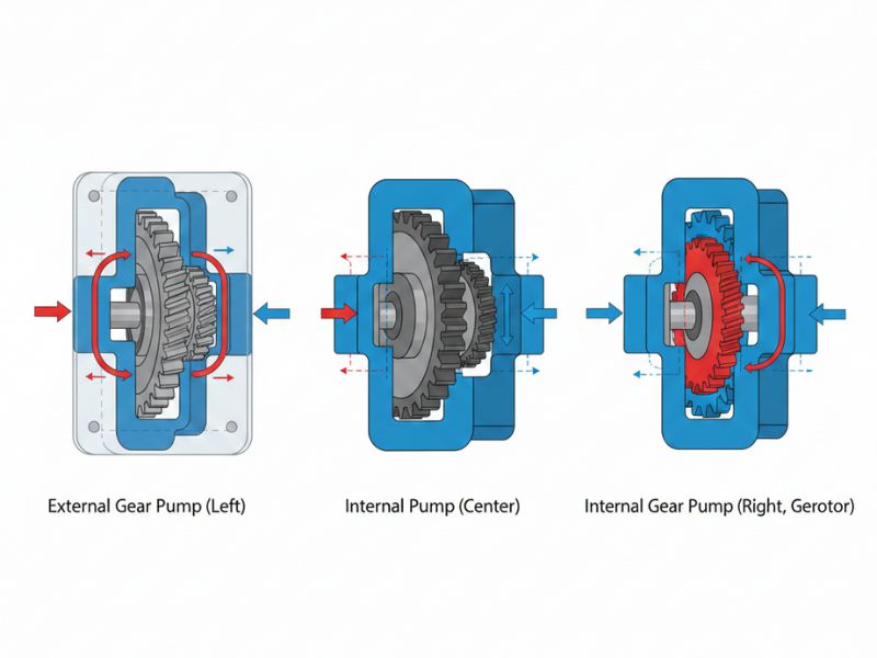
Gear pumps are broadly classified into two main categories based on their design and operation: External Gear Pumps and Internal Gear Pumps.
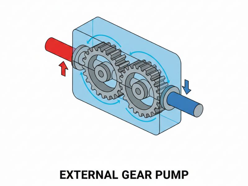
External gear pumps use two identical gears with external teeth mounted on parallel shafts to generate flow. As the gears rotate, fluid is drawn into the pump at the inlet port where the gears separate. The liquid is then trapped between the gear teeth and the pump casing, carried around the outer periphery, and discharged at the outlet port as the gears mesh.
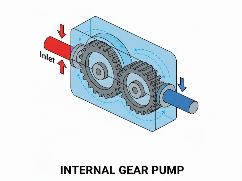
Internal gear pumps consist of an inner (drive) gear, a larger outer gear with internal teeth, and a crescent-shaped spacer between them. As the gears rotate, fluid enters as the gears un-mesh, travels between the inner and outer gears, and is pushed out smoothly as the gears re-mesh. The crescent forms a seal separating suction and discharge areas.
| Feature | External Gear Pump | Internal Gear Pump |
|---|---|---|
| Design | Two identical gears side by side | Internal rotor with external idler gear and crescent seal |
| Pressure Capability | Higher pressures (up to 70 kg/cm²) | Moderate to high (typically 40–50 kg/cm²) |
| Viscosity Range | Low to medium viscosity | Excellent for high viscosity (up to 100,000 CST) |
| Temperature Tolerance | Standard temperature range | Handles high temperatures; steam jacketed options |
| Noise Level | Higher flow pulsation, more noise | Quieter, smoother operation |
| Flow Direction | Bi-directional with spur gears; unidirectional with herringbone | Always bi-directional |
| Cost | More economical, simpler construction | Higher cost due to complex machining |
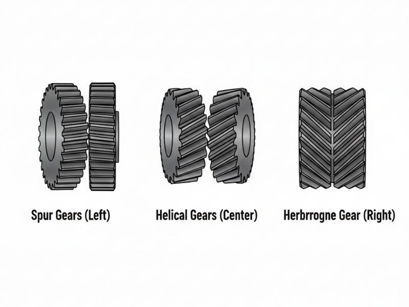
Gear pumps use different gear configurations depending on the application requirements:
| Model No. | Suction X Delivery Size | Capacity Range (LPM) | Standard Pump Speed (RPM) |
|---|---|---|---|
| UA-5 | 3/8'' X 3/8'' | 2 to 5 | 1440 |
| UA-10 | ½'' X ½'' | 6 to 20 | 1500 |
| UA-15 | ¾'' X ¾'' | 21 to 30 | 1500 |
| UA-20 | 1'' X 1'' | 51 to 75 | 1500 |
| UA-25 | 1 ½'' X 1 ½'' | 76 to 100 | 1500 |
| UA-50 | 2'' X 2'' | 161 to 225 | 1500 |
| UA-100 | 3'' X 3'' | 351 to 550 | 1500 |
| UA-200 | 4'' X 4'' | 751 to 1200 | 1500 |
| UA-400 | 4'' X 4'' | 1201 to 1800 | 960 |
| UA-600 | 6'' X 6'' | 1801 to 2500 | 960 |
| UA-800 | 8'' X 8'' | 2501 to 6000 | 720 |
Model Options: Without Relief Valve (UA), With Relief Valve (UAV), Mechanical Seal (UAM), Flange Mounted (UAF), External Bearing (UAX), Steam Jacketed (UASJ), Higher Pressure (UAHP), Stainless Steel (UAS & UASS).
Selection Checklist: Answer these questions before selecting a gear pump:
Also Read: Gear Pump Maintenance Best Practices
No. Gear pumps rely on the pumped fluid for lubrication and cooling. Running dry, even briefly, causes rapid wear, heat expansion, and permanent damage to gears and casing.
UA Series gear pumps can handle pressures up to 70 kg/cm² with highly precision profile ground gears.
Gear pumps are ideal for lubricating and non-lubricating liquids such as oils, fuels, resins, polymers, adhesives, soaps, chocolate, and high-viscosity chemicals. For non-lubricating fluids, external bearing designs are recommended.
Yes. Because gear pumps are positive displacement, they continue building pressure if discharge is blocked. A built-in relief valve protects the system from overpressure.
Materials include cast iron, stainless steel, gun metal, bronze, and super alloys. Gears can be carbon steel or hardened stainless steel. Sealing options include oil seals, mechanical seals, and gland packing.
External gear pumps use two identical external gears and are best for higher pressures and lower viscosities. Internal gear pumps use an internal and external gear with a crescent seal and excel at high-viscosity fluids with quieter operation.