
Unique Pump Systems, Kailash Industrial Complex, Vikhroli (W)
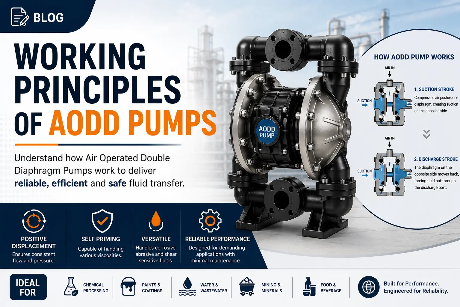
An AODD pump works by using compressed air to push two diaphragms back and forth on a shared connecting rod. As one diaphragm is pushed forward to discharge fluid, the other is pulled back to draw fluid in. Four check balls control flow direction, and an air distribution valve automatically reverses the stroke.
Air operated double diaphragm pumps look almost too simple to be as capable as they are. There is no motor, no rotating shaft in the fluid, no gearbox and no seal to leak. Yet the same basic machine transfers acid in a chemical plant, ketchup in a food factory, slurry on a mine site and adhesive in a furniture workshop.
People search for the working principle of AODD pumps for three reasons. Some are engineers specifying a pump and want to understand what they are buying. Some are maintenance technicians trying to diagnose a pump that has stopped cycling. Some are students who need the sequence explained without the marketing language.
This article explains all of it in plain English:
By the end you will be able to explain the working principle to someone else — which is the real test of understanding.
An AODD pump — air operated double diaphragm pump — is a reciprocating positive displacement pump powered entirely by compressed air. "Double diaphragm" means it has two flexible diaphragms working together, connected by a common shaft, so that one chamber always fills while the other empties.
The result is near-continuous flow from a reciprocating machine, with no electrical connection, no dynamic seal and no close-running metal parts in contact with the fluid.
A modern aodd pump is built from just a handful of subassemblies, which is exactly why it is so easy to maintain in the field.
| Component | Function | Typical Materials |
| Air distribution valve | Directs compressed air alternately to each air chamber and reverses the stroke | Acetal, aluminium, conductive polymer |
| Pilot valve | Signals the main air valve to shift at the end of each stroke | Acetal, stainless steel |
| Diaphragms (×2) | Separate air from fluid and displace the liquid | Santoprene, PTFE, Buna-N, EPDM, Viton, polyurethane |
| Connecting rod / shaft | Links both diaphragms so they move together | Stainless steel |
| Air chambers (×2) | Contain the compressed air acting on the back of each diaphragm | Aluminium, cast iron, polypropylene, PVDF |
| Liquid chambers (×2) | Contain the fluid being pumped | Aluminium, stainless steel, PP, PVDF |
| Check balls (×4) | Allow flow in one direction only | PTFE, Santoprene, stainless steel, polyurethane |
| Ball seats (×4) | Provide a sealing surface for each ball | Same family as balls |
| Suction manifold | Collects fluid entering both liquid chambers | Matches body material |
| Discharge manifold | Combines output from both liquid chambers | Matches body material |
| Muffler / exhaust | Vents spent air and reduces noise | Plastic or metal |
Compressed air enters the pump and is directed by the air distribution valve to the back of diaphragm A. That air pressure pushes diaphragm A forward, forcing fluid out of liquid chamber A through the upper discharge ball. Because both diaphragms share one connecting rod, diaphragm B is pulled backwards at the same time, creating a vacuum in liquid chamber B that pulls fluid in through the lower suction ball. At the end of the stroke, a pilot valve triggers the air valve to switch sides. Air now goes to diaphragm B, the spent air from chamber A exhausts through the muffler, and the process reverses. This continues automatically for as long as air is supplied.
Result: each full cycle produces two discharge events, one from each chamber. This is why the flow from an AODD pump, while pulsating, is far smoother than from a single-diaphragm pump.
| Stage | Diaphragm A | Diaphragm B | Suction Ball A | Discharge Ball A | Suction Ball B | Discharge Ball B |
| Stroke 1 | Discharging | Filling | Closed | Open | Open | Closed |
| Reversal | End of travel | End of travel | Transitioning | Transitioning | Transitioning | Transitioning |
| Stroke 2 | Filling | Discharging | Open | Closed | Closed | Open |
The air distribution valve is the brain of the pump. Everything else is mechanically passive.
Its job is to sense that a stroke has finished and switch the air supply to the other side — without any electronics, sensors or external control.
How it does this:
Design variations:
| Valve Type | Characteristics | Best For |
| Non-lubricated air valve | Runs on clean dry air, no lubricator needed | Most modern installations |
| Lubricated air valve | Requires oil mist in the air supply | Older or heavy-duty designs |
| Externally serviceable valve | Can be replaced without opening the fluid side | High uptime requirements |
| Anti-stall / anti-icing design | Resists moisture freezing and mid-stroke stalling | Cold climates, wet air supply |
If a pump stops mid-stroke and will not restart, the air valve or pilot valve is the first place to look — not the diaphragms.
Check balls are simple gravity and pressure-operated non-return valves. Each liquid chamber has two:
Practical implications:
Because the pump relies on gravity to help seat the balls, most AODD pumps perform best mounted vertically with the discharge manifold at the top.
Self-priming ability comes from the fact that the pump can move air just as easily as it moves liquid.
On start-up with a dry suction line:
Dry suction lift of 4–5 metres is typical, and wetted suction lift can reach 7–9 metres depending on design and fluid. Heavier balls, larger suction pipe and a shorter suction run all improve this.
These two abilities set AODD pumps apart from nearly every rotary pump.
Dry running is safe because there are no close-running metal surfaces relying on the fluid for lubrication or cooling. The diaphragms flex in air exactly as they do in liquid. Nothing overheats, nothing scores. A rotary pump under the same conditions would destroy its clearances within minutes.
Dead-heading is safe because the pump stalls instead of building destructive pressure. When the discharge is closed, pressure in the liquid chamber rises until it balances the air pressure behind the diaphragm. At that point the diaphragm stops moving, the air valve stops shifting, and the pump simply holds. It restarts automatically the instant the discharge opens.
This behaviour is exploited deliberately in applications such as:
Compare that with a rotary positive displacement pump such as a gear pump, which will keep generating pressure against a closed valve until a relief valve opens or something in the system fails. Every rotary positive displacement installation needs a properly set relief valve; an AODD pump does not.
Standard AODD pumps are 1:1 ratio machines. The air pressure acting on the back of the diaphragm equals the maximum liquid pressure the pump can generate.
| Air Inlet Pressure | Maximum Liquid Discharge Pressure |
| 2 bar | 2 bar |
| 4 bar | 4 bar |
| 6 bar | 6 bar |
| 7 bar | 7 bar |
What this means in practice:
| Part | Material Options | Selection Driver |
| Body / manifolds | Aluminium, cast iron, 316 SS, polypropylene, PVDF, conductive acetal | Chemical resistance, temperature, abrasion, ATEX |
| Diaphragms | Santoprene, PTFE, Buna-N, EPDM, Viton, polyurethane, neoprene | Chemistry, temperature, flex life, abrasion |
| Balls and seats | PTFE, Santoprene, stainless steel, polyurethane | Chemistry, weight for suction, abrasion resistance |
| O-rings | PTFE, EPDM, Viton, Buna-N | Chemistry and temperature |
| Air section | Acetal, aluminium, conductive polymer | Environment and ATEX classification |
Key point for hazardous areas: static electricity generated by flowing fluid must have a path to earth. In flammable atmospheres, specify conductive materials throughout and bond the pump to a verified earth point.
| Advantages | Limitations |
| Runs dry indefinitely without damage | Pulsating flow requires damping for smooth delivery |
| Dead-heads safely and restarts automatically | Compressed air is an expensive energy source |
| No dynamic seal, so no seal leakage | Limited to about 8 bar in standard 1:1 designs |
| Excellent self-priming and suction lift | Flow capacity limited compared with centrifugal pumps |
| Handles solids, slurries and abrasives | Diaphragms are consumable items |
| Portable, no electrical supply required | Noisy without a good muffler |
| Naturally suited to hazardous areas | Air valve can ice up with wet air |
| Simple field repair with basic tools | Requires reliable compressed air infrastructure |
| Variable flow simply by adjusting air | Not ideal for very high viscosity above 20,000 cP |
| Criterion | AODD | Centrifugal | Gear Pump | Lobe Pump | Peristaltic |
| Principle | Reciprocating PD | Kinetic | Rotary PD | Rotary PD | Rotary PD |
| Dry run safe | Yes | No | No | No | Yes |
| Dead-head safe | Yes | No | No | No | No |
| Solids handling | Excellent | Poor | Poor | Good | Excellent |
| Shear on product | Low | High | Medium | Very low | Very low |
| Flow smoothness | Pulsating | Smooth | Smooth | Smooth | Pulsating |
| Max pressure | ~8 bar | Varies | High | Medium | Medium |
| Energy efficiency | Low | High | High | High | Medium |
| Seal required | None | Yes | Yes | Yes | None |
| Hygienic versions | Yes | Yes | Limited | Excellent | Yes |
Where product must be moved gently at high viscosity in a hygienic process — creams, yoghurt, pastes, fruit preparations — a lobe pump gives smooth, low-shear, pulsation-free flow that a diaphragm pump cannot match. On rotary pumps like these, the reliability of the installation depends heavily on the sealing arrangement, and a correctly specified mechanical seal is what keeps product in and contamination out.
| Industry | Typical Fluids | Why AODD Works |
| Chemical processing | Acids, alkalis, solvents | Seal-free containment, chemical-resistant materials |
| Paint and coatings | Paints, resins, pigments | Handles viscosity, ATEX safe, portable |
| Food and beverage | Sauces, syrups, juices | Sanitary designs, gentle handling, CIP options |
| Pharmaceutical | Slurries, WFI, intermediates | Contamination-free, PTFE wetted parts |
| Mining and quarrying | Slurries, sludge, sump water | Abrasion tolerance, dry run, no electricity |
| Wastewater treatment | Sludge, polymer, scum | Solids handling, self-priming |
| Printing and packaging | Inks, adhesives | Precise low-flow control, easy cleaning |
| Automotive | Oils, coolants, degreasers | Portable transfer, drum emptying |
| Ceramics and construction | Glazes, grouts, slurries | Abrasive-duty elastomers |
| Marine | Bilge, fuel, oily water | No electrics, self-priming, dry run safe |
| Symptom | Likely Cause | Action |
| Pump will not start | No air, closed valve, air valve stuck | Check air at inlet, cycle valve, inspect air valve |
| Pump stalls mid-stroke | Pilot valve fault, iced air valve, low air pressure | Check air dryness and pressure, service air valve |
| Cycles but no flow | Suction air leak, closed valve, ball held open by debris | Check suction joints, open valves, inspect balls |
| Reduced flow | Worn seats, low air volume, high viscosity, clogged strainer | Inspect seats, verify air CFM, clean strainer |
| Product in air exhaust | Ruptured diaphragm | Stop pump, replace both diaphragms |
| Air leaking from exhaust when stalled | Worn air valve seals or O-rings | Service air valve kit |
| Excessive noise | Missing or blocked muffler, cavitation | Fit muffler, check suction restriction |
| Ice on the pump | Moisture in compressed air | Install dryer or coalescing filter |
| Erratic pulsing | Air in fluid, partly blocked suction | Check for leaks and restrictions |
| Short diaphragm life | Over-speeding, wrong elastomer, excessive temperature | Slow the pump, review material selection |
Golden diagnostic rule: if the pump is cycling normally but not delivering, the fault is on the fluid side. If the pump is not cycling at all, the fault is on the air side.
| Myth | Fact |
| "AODD pumps have no moving parts" | They have several — diaphragms, shaft, balls and an air valve — but no rotating shaft in the fluid |
| "The air valve is electrically controlled" | It is entirely pneumatic and mechanical, which is why the pump is safe in hazardous areas |
| "You can increase pressure by adding a bigger air line" | A bigger line reduces pressure drop but cannot exceed compressor pressure; the ratio stays 1:1 |
| "A leaking exhaust always means a broken diaphragm" | Air-only leakage usually indicates worn air valve seals; product in the exhaust indicates a diaphragm rupture |
| "AODD pumps cannot be used for accurate dosing" | With stroke counting or metering controls they can dose repeatably, though not to metering pump accuracy |
| "Flow is completely pulse-free with two diaphragms" | Two diaphragms halve the pulsation of a single diaphragm design but do not eliminate it |
| "Any air pressure works" | Below about 2 bar most pumps stall or cycle erratically |
| Task | Frequency | Notes |
| Visual leak check | Daily or per shift | Look at manifolds, exhaust and joints |
| Drain air receiver and filter bowl | Weekly | Prevents moisture reaching the air valve |
| Check air inlet pressure while running | Monthly | Confirms no supply degradation |
| Inspect suction strainer | Monthly | Restriction reduces flow and causes cavitation |
| Check manifold bolt torque | Quarterly | Elastomer gaskets relax over time |
| Inspect balls and seats | 6 months or on flow drop | Worn seats cause silent efficiency loss |
| Replace diaphragms | Based on logged life | Always replace both together |
| Service air valve kit | 12–24 months or on fault | Externally serviceable designs make this quick |
| Full overhaul | 2–4 years typical | Replace all elastomers and O-rings |
Compressed air is directed alternately behind two diaphragms connected by a common shaft. As air pushes one diaphragm forward to discharge fluid, the other is pulled back to draw fluid in. Four check balls control flow direction, and an air distribution valve automatically reverses the stroke at each end of travel.
It is a purely pneumatic spool or shuttle valve with two positions. In each position it feeds compressed air to one air chamber while venting the other to exhaust. At the end of a stroke, the connecting rod opens a pilot passage, and pilot air pressure shifts the main spool across to reverse the stroke.
Each of the two liquid chambers needs one suction ball and one discharge ball to ensure fluid can only travel one way. The suction ball lifts on the filling stroke and seats on the discharge stroke, while the discharge ball does the opposite, keeping flow moving continuously toward the discharge manifold.
Yes. There are no close-running metal parts, no seal and no bearing relying on the fluid for lubrication or cooling. The diaphragms simply flex in air. This makes the pump ideal for emptying tanks, sumps and drums where the supply will run out during operation.
The pump stalls safely. Liquid pressure rises until it balances the air pressure behind the diaphragm, at which point the diaphragms stop moving and the air valve stops shifting. No pressure build-up damages the system, and the pump restarts automatically as soon as the discharge is reopened.
Most are 1:1, meaning maximum liquid discharge pressure equals the air inlet pressure at the pump. Supplying 6 bar of air gives a maximum of about 6 bar of liquid pressure. Higher ratio designs such as 2:1 use a larger air piston to achieve higher fluid pressures for spray applications.
Dry suction lift is typically 4–5 metres, and wetted lift can reach 7–9 metres depending on design, ball weight, fluid properties and suction line size. Shorter, larger-diameter suction pipework with airtight joints gives the best results.
The air side is working, so the problem is on the fluid side. Common causes include an air leak in the suction line, a closed or blocked valve, a ball held off its seat by debris, worn seats allowing back-flow, or fluid too viscous to fill the chamber at the current cycle speed.
Moisture in the compressed air expands and cools rapidly as it passes through the air valve, forming ice that jams the spool. Fitting an air dryer or coalescing filter, draining the receiver regularly and selecting an anti-icing air valve design all resolve the problem.
The clearest sign is product appearing in the air exhaust or muffler. Other indicators include a sudden drop in flow, erratic cycling, or fluid appearing in the air line. Stop the pump immediately and replace both diaphragms together, since the second is usually the same age.
Most modern designs use non-lubricated air valves and require only clean, dry air. Adding oil to a non-lubricated design can wash out factory lubricant and cause sticking. Always follow the manufacturer's specification, and never mix lubricated and non-lubricated practice on the same pump.
Yes, which is one of their major advantages. With no electric motor and no ignition source, they are widely used in ATEX-classified zones. Specify conductive wetted and non-wetted materials, an appropriate ATEX certification, and bond the pump to a verified earth point to dissipate static charge.
The working principle of an AODD pump comes down to one elegant idea: use air pressure on one side of a flexible membrane to move liquid on the other, and let a self-reversing air valve do the sequencing. That simplicity is why the pump can run dry, stall safely, prime itself, pass solids and work without electricity.
Understand the cycle and the fault diagnosis becomes obvious. Cycling but not pumping means look at the fluid side. Not cycling at all means look at the air side. Almost every AODD problem resolves down that path.