Unique Pump Systems, Kailash Industrial Complex, Vikhroli (W)
An Air Operated Double Diaphragm (AODD) pump is a positive displacement pump that uses compressed air as its motive force. It converts the pressure energy of compressed air into the reciprocating mechanical motion that moves fluid through the pump — without any electrical connection, mechanical shaft seal, or rotating component in contact with the fluid. This combination of simplicity, versatility, and inherent safety is why AODD pumps are found across chemical plants, pharmaceutical facilities, mining operations, food processing lines, and wastewater treatment plants worldwide. Understanding how an AODD pump works — not just the summary principle, but the mechanics of each component, each stroke phase, and each control variable — gives engineers and maintenance teams the knowledge to select the right pump, set it up correctly, optimise its performance, and diagnose problems quickly. This guide also covers the gear pump-adjacent context for fluid handling system designers who need to understand where each pump type fits in a process.
Also Read: AODD Pumps vs EODD Pumps
Before examining how the pump operates, it is essential to understand what every component does. An AODD pump has remarkably few parts, which is the foundation of its reliability — but each part plays a precise role in the pumping cycle.
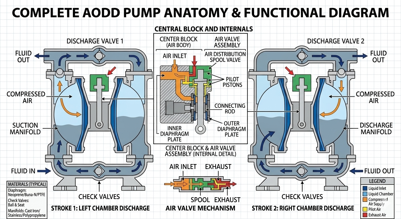
The center block is the structural core of the pump, housing the air distribution valve and connecting the two pump bodies. Compressed air enters the pump through a single inlet port on the center block. Inside the center block, the air distribution valve — also called the air shift valve or spool valve — directs this air alternately to the left and right air chambers. The center block also contains the shaft bore through which the connecting shaft passes between the two diaphragms.
The center block is typically made from the same material as the pump body — aluminium, polypropylene, or stainless steel depending on the application. In hazardous area installations, the center block must be grounded (earthed) to prevent static charge accumulation.
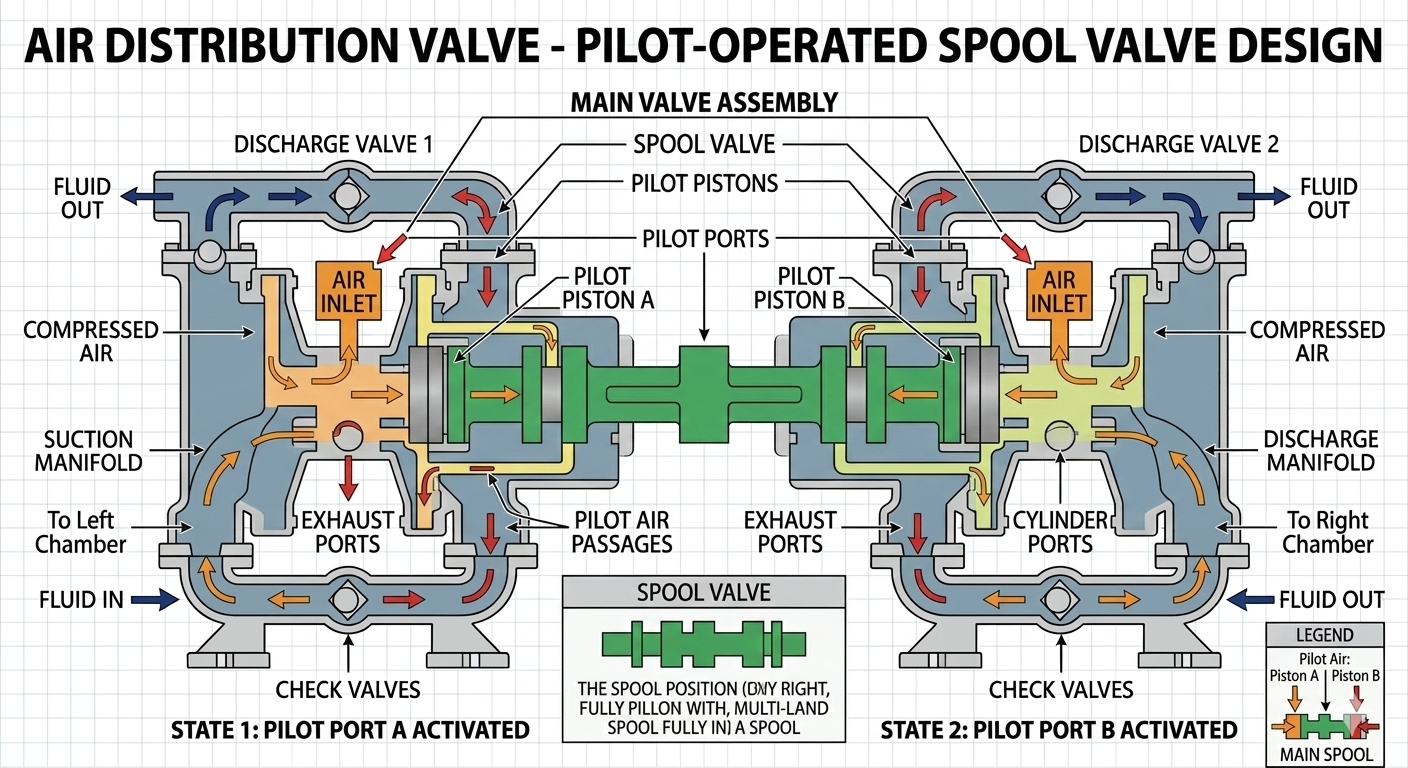
The air distribution valve is the most mechanically critical component in the AODD pump. It is responsible for automatically switching the compressed air supply from one air chamber to the other at the end of each stroke — without any external control signal, solenoid, or operator input.
Most industrial AODD pumps use one of two air valve designs:
The air valve is the most common source of AODD pump problems. A sticking or worn spool valve causes the pump to stall mid-cycle, run irregularly, or fail to restart after a dead-head condition. Regular cleaning of the valve (especially when using dirty or wet compressed air) is the most effective preventive maintenance action for AODD pump reliability.
Each AODD pump has two diaphragms — one on each side of the center block. The diaphragm is the only dynamic component in direct contact with both the fluid and the compressed air. Its entire function is to act as a flexible, impermeable separator between the air chamber (behind it) and the liquid chamber (in front of it).
The diaphragm flexes outward on the discharge stroke (air pressure pushes it into the liquid chamber, reducing liquid chamber volume and forcing fluid out) and inward on the suction stroke (the opposite diaphragm's discharge stroke pulls it back via the connecting shaft, expanding the liquid chamber and drawing fluid in).
A diaphragm consists of three elements assembled together:
A single rigid rod runs through the center block, connecting the inner plates of both diaphragms. When compressed air pushes the right diaphragm outward on its discharge stroke, the shaft simultaneously pulls the left diaphragm inward on its suction stroke. The two diaphragms are mechanically coupled — they always move in opposite directions simultaneously. This is the 'double diaphragm' aspect of AODD design, and it is what allows the pump to produce continuous (though pulsating) flow rather than the single-direction flow of a single-diaphragm pump.
The shaft operates in a lubricated bore in the center block. In most designs, the process fluid provides lubrication to the shaft bore — another reason AODD pumps are not suited to extended dry running at high speed.
Each pump body contains a liquid chamber — the cavity between the diaphragm face and the pump body wall. The liquid chamber volume changes between maximum (when the diaphragm is fully pulled inward on suction stroke) and minimum (when the diaphragm is fully pushed outward on discharge stroke). The volumetric difference between these two positions is the stroke volume — the amount of fluid displaced per half-cycle.
Four check valves control the direction of fluid flow through the pump — two inlet valves (one per liquid chamber) and two outlet valves (one per liquid chamber). Each check valve allows flow in one direction only.
In most AODD pump designs, these are ball check valves — a sphere (ball) that seats against a precision-machined valve seat to block reverse flow, and lifts off the seat to allow forward flow. The ball is made from PTFE, stainless steel, ceramic, rubber, or other materials depending on fluid compatibility.
The check valves operate purely on pressure differential — no springs, no external actuation:
Check valve ball wear or contamination is the second most common cause of AODD pump problems after air valve issues. A worn ball or contaminated seat allows backflow — the pump cycles but delivers less flow than expected, or fails to hold pressure at shutoff. Regular inspection and replacement of check valve balls and seats is essential in abrasive or particle-laden fluid service.
The inlet manifold connects the fluid supply source to both liquid chambers through the two inlet check valves. The outlet manifold collects fluid from both liquid chambers (through the two outlet check valves) and delivers it to the discharge line. The manifold arrangement is what allows both chambers to share a single inlet and a single outlet — simplifying piping connections to two ports regardless of pump size.
Although technically external to the pump body, the FRL unit is an essential part of the AODD pump system. It is installed on the compressed air supply line immediately upstream of the pump's air inlet:
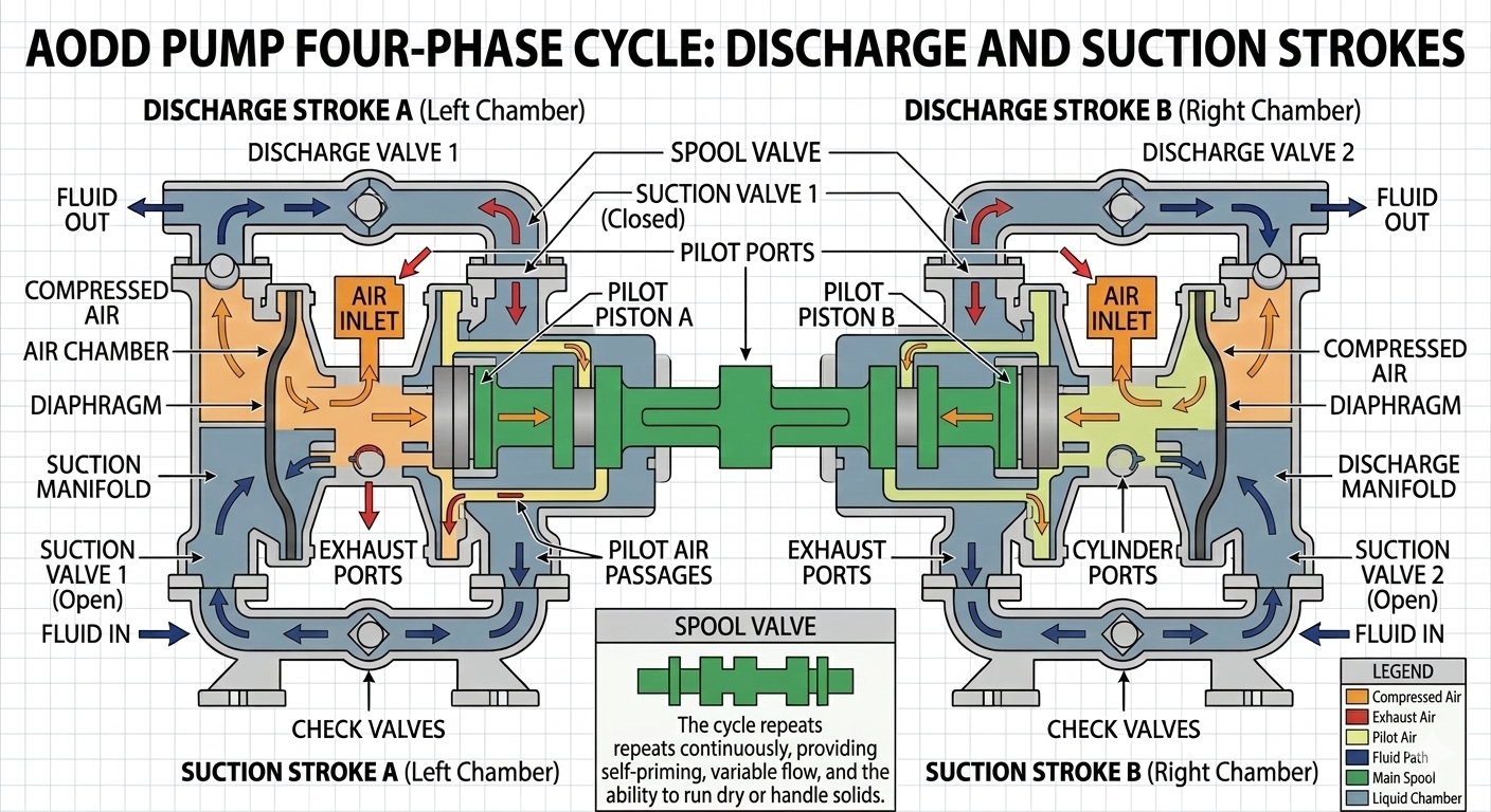
One complete pumping cycle consists of two half-cycles (one per diaphragm). Each half-cycle has two simultaneous events — one diaphragm on its discharge stroke while the other is on its suction stroke. Here is a frame-by-frame breakdown of the complete cycle:
What is happening in the air section:
The air distribution valve is in its right position. Compressed air flows from the inlet through the valve and into the right air chamber — the space between the right pump body wall and the back (outer plate) of the right diaphragm. Air pressure builds behind the right diaphragm.
What is happening on the right side:
Air pressure pushes the right diaphragm outward (away from the center block and toward the right pump body wall). This reduces the volume of the right liquid chamber. The pressure rise in the right liquid chamber pushes the right inlet ball firmly onto its seat (closing the inlet) and simultaneously lifts the right outlet ball off its seat. Fluid in the right liquid chamber is forced out through the right outlet check valve and into the outlet manifold under pressure.
What is happening on the left side simultaneously:
The connecting shaft is rigidly attached to both diaphragm inner plates. As the right diaphragm moves outward, the shaft pulls the left diaphragm inward (toward the center block). This increases the volume of the left liquid chamber, creating a low-pressure zone inside it. The pressure in the left liquid chamber drops below the inlet supply pressure — the left inlet ball lifts off its seat and fluid flows into the expanding left liquid chamber. The left outlet ball remains on its seat because discharge pressure is higher than the low-pressure chamber.
What is happening with the air exhaust:
While the right side is on its discharge stroke, the left air chamber (the space behind the left diaphragm) is open to atmosphere through the air valve's exhaust port. As the left diaphragm is pulled inward by the shaft, the volume of the left air chamber decreases — the air behind the left diaphragm exhausts to atmosphere through the valve's exhaust port and exits through the pump's air exhaust (muffler). This exhaust is the source of the characteristic rhythmic 'chuff' sound of an operating AODD pump.
As the right diaphragm reaches the end of its discharge stroke (the diaphragm is fully extended and the right liquid chamber is at minimum volume), the pilot mechanism in the air valve is triggered. In a pilot-operated design, a small pilot passage opens as the diaphragm reaches its travel limit, routing a small volume of compressed air to act against the end of the valve spool. The pressure differential shifts the spool to its left position.
The valve shift is fast — typically completing in milliseconds. Once shifted:
The speed of this valve shift determines the smoothness of the flow transition between strokes. A fast, decisive valve shift produces a sharper pulse at stroke reversal; a sluggish valve (worn spool, dirty passages, insufficient air pressure) produces a longer pause at stroke reversal, reducing effective flow rate and creating irregular cycling.
This phase is the mirror image of Phase 1. Compressed air now enters the left air chamber, pushing the left diaphragm outward. The connecting shaft simultaneously pulls the right diaphragm inward. The left liquid chamber discharges through the left outlet check valve; the right liquid chamber fills through the right inlet check valve. Air exhausts from the right air chamber.
As the left diaphragm reaches the end of its discharge stroke, the pilot mechanism triggers again and the valve shifts back to its right position — returning to Phase 1. One complete pumping cycle (comprising two half-cycles, one per diaphragm) is now complete.
The number of complete cycles per minute is the stroke rate. Flow rate is:
The factor of 2 accounts for both diaphragms discharging once per cycle. At a stroke volume of 0.5 litres per diaphragm and a stroke rate of 60 cycles/min, the pump delivers 0.5 × 60 × 2 = 60 LPM.
This is one of the most important operational relationships in AODD pump operation — and one the competitor's guide does not address at all. Understanding it is essential for correct pump setup and troubleshooting.
Higher air supply pressure increases the force on the diaphragm. This moves the diaphragm faster — completing each stroke in less time — which increases the stroke rate (cycles per minute). A higher stroke rate means more fluid displaced per minute, so flow rate increases.
However, this relationship is not linear. As discharge back-pressure increases (e.g., higher system pressure, longer discharge line, partially closed valve), the diaphragm must work harder against the resistance. Stroke rate decreases. At the point where discharge back-pressure equals supply air pressure, the pump stalls — strokes stop. This is the pump's dead-head condition.
Key operational rule: An AODD pump can never develop a discharge pressure higher than its supply air pressure. To pump against 4 bar of back-pressure, you need at least 4 bar of supply air pressure. In practice, always maintain supply air pressure at least 0.5–1 bar above the maximum expected system back-pressure to ensure the pump cycles reliably.
The maximum pressure an AODD pump can develop against a closed discharge (its shut-off or dead-head pressure) is approximately equal to the supply air pressure. This is a direct consequence of the diaphragm being the pressure-generating element — it pushes on the fluid with the same force the air pushes on it, minus internal friction losses.
| Supply Air Pressure (bar) | Approximate Max Discharge Pressure (bar) | Typical Flow Effect |
|---|---|---|
| 2 bar | ~1.8 bar | Low flow; suitable only for very low back-pressure applications |
| 4 bar | ~3.6 bar | Standard light duty; covers most drum emptying, transfer applications |
| 6 bar (typical plant supply) | ~5.5 bar | Standard industrial duty; covers most chemical transfer and process applications |
| 7–8 bar | ~6.5–7.5 bar | High pressure duty; filter press feed, elevated tank filling |
| 8.5 bar (typical max) | ~8 bar | Maximum for most AODD pumps — check manufacturer's rated maximum |
Running an AODD pump at maximum air pressure does not give the best efficiency. The pump uses the most air (Nm³/hr) when running at maximum speed against low back-pressure — most of the energy goes into moving the diaphragm quickly rather than doing useful work against pressure. The most energy-efficient operating point is at moderate stroke rate with moderate discharge pressure.
A practical guideline: set the air supply regulator to the minimum pressure that achieves the required flow rate at the actual system back-pressure. Every unnecessary bar of supply air pressure increases compressed air consumption and operating cost without increasing useful output.
Self-priming means the pump can draw fluid up from a source below the pump inlet — it does not need to be pre-filled with fluid before starting. AODD pumps are self-priming because their diaphragm mechanism creates suction without relying on fluid in the pump to generate the necessary pressure differential.
When the diaphragm pulls inward on its suction stroke, it creates a partial vacuum in the liquid chamber. Atmospheric pressure acting on the fluid surface in the supply tank pushes fluid up the suction line toward this low-pressure zone. The maximum height the fluid can be lifted is determined by atmospheric pressure minus the vapour pressure of the fluid:
For water at sea level: 101.3 kPa / 9.81 kN/m³ = approximately 10.3 metres. In practice, friction losses in the suction line, air valve pressure drop, and the need to maintain positive pressure at the inlet valve reduce the achievable suction lift to 4–7 metres for most AODD pumps.
When the discharge valve is closed or the downstream system is blocked, discharge back-pressure rises until it equals supply air pressure. At this point, neither diaphragm can complete its stroke — the pump stalls. The air valve may continue to shift rapidly (hunting), or it may stall in one position depending on design.
This is a safe condition for the pump — an AODD pump can dead-head indefinitely without damage. No pressure is built up beyond the supply air pressure; the relief valve is not needed (unlike centrifugal pumps, where a dead-head condition causes rapid temperature rise from the recirculating fluid). However, the compressed air continues to be consumed during the hunting phase — a cost consideration for long dead-head periods.
AODD pumps can run dry (with no fluid in the pump) without immediate damage — the diaphragms continue to flex and the air valve continues to shift. However, dry running is not recommended for extended periods because:
For applications where dry running is possible (tank emptying, intermittent supply), AODD pumps are far more tolerant than centrifugal pumps or mechanically-sealed rotary pumps, but dry-run protection (a float switch cutting the air supply when the tank empties) is best practice.
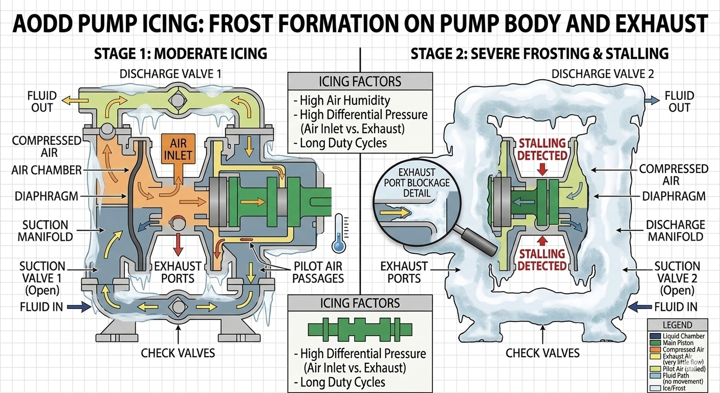
One of the least-discussed but practically important AODD pump phenomena is pump body icing — the formation of frost or ice on the pump's external surfaces and air exhaust, particularly in cold environments or high-cycle operations.
When compressed air expands through the air distribution valve and exhausts from the pump, it undergoes a rapid pressure drop. According to the physics of adiabatic expansion (the Joule-Thomson effect), expanding gas cools. The greater the pressure drop, the greater the temperature drop. At a typical plant air pressure of 6 bar expanding to atmosphere (1 bar), the air temperature can drop by 15–25°C at the exhaust point.
If the ambient temperature is already moderate (20–25°C), this cooling drops the exhaust air and surrounding pump body temperature to 0°C or below — causing moisture in the exhaust air to freeze. The ice forms on the exhaust muffler, external pump surfaces, and in extreme cases inside the air valve passages themselves.
Air consumption is the volume of compressed air used per unit time, expressed in Nm³/hr (Normal cubic metres per hour) or SCFM (Standard cubic feet per minute). It directly determines the load on the compressed air system and the operating energy cost of the pump.
Air consumption depends on three variables:
Example: A 1-inch AODD pump with 0.1 litre stroke volume running at 80 cycles/min on 5 bar supply air:
Air = 0.0001 m³ × 80 × 60 × (6 bar abs / 1 bar abs) = 2.88 Nm³/hr
At a compressed air cost of ₹3/Nm³ (typical Indian industrial tariff), this pump costs approximately ₹8.64/hr to operate in compressed air alone. A 3-inch pump running continuously at 100 cycles/min on 6 bar would consume 30–50 Nm³/hr — representing a significant energy cost in continuous service, which is one of the primary drivers for conversion to EODD in suitable applications.
| Pump Size | Typical Stroke Volume | Air Consumption at 6 bar, 60 cycles/min | Approx. Annual Air Cost (₹3/Nm³, 16hr/day, 300 days) |
|---|---|---|---|
| ½ inch | ~0.02 L | ~0.35 Nm³/hr | ~₹5,040/year |
| 1 inch | ~0.1 L | ~1.73 Nm³/hr | ~₹24,912/year |
| 1.5 inch | ~0.35 L | ~6.0 Nm³/hr | ~₹86,400/year |
| 2 inch | ~0.8 L | ~13.8 Nm³/hr | ~₹1,98,720/year |
| 3 inch | ~2.5 L | ~43 Nm³/hr | ~₹6,19,200/year |
These figures illustrate why compressed air cost is a major consideration for large, continuously-operating AODD pumps. A 3-inch AODD pump running 16 hours/day consumes over ₹6 lakh/year in compressed air alone. For permanent installations in safe areas, this operating cost makes an EODD conversion financially compelling within 12–18 months.
AODD pumps occasionally exhibit irregular operating patterns — surging (sudden flow bursts), stuttering (rapid incomplete cycles), or stalling (stopping mid-stroke). Understanding the cause of each helps maintenance teams diagnose and correct problems quickly.
| Symptom | Most Likely Cause | Diagnostic Check | Corrective Action |
|---|---|---|---|
| Pump cycles slowly or stops under load | Supply air pressure insufficient for system back-pressure | Measure air pressure at pump inlet under operating load | Increase supply pressure or reduce downstream restriction |
| Pump stutters rapidly — many short cycles, no full stroke | Air valve not shifting fully — dirty or worn spool | Remove and inspect air valve; check for contamination or scoring | Clean valve passages; replace spool and seals if worn |
| One side only pumping — asymmetric output | Check valve on one side stuck open or closed | Check for product discharge on suction side (backflow) or no suction on one side | Inspect and replace ball and seat on affected check valve |
| Flow rate declining gradually over time | Check valve wear allowing backflow across both valves | Test pump output against rated spec; listen for backflow sound | Replace all four check valve balls and seats as a set |
| Pump runs but no flow from discharge | Both outlet check valves blocked or both inlet check valves blocked | Disconnect manifolds and test valves individually | Clear blockage or replace valves |
| Air continuously leaking from exhaust even at dead-head | Air valve spool not seating correctly — worn or contaminated | Listen for continuous air exhaust (not the pulsed exhaust of cycling) | Replace air valve spool and seals |
| Pump body icing / frequent stalling in cold weather | Moisture in compressed air supply freezing in valve passages | Check FRL separator bowl; inspect exhaust for ice | Service moisture separator; add air dryer to supply |
| Diaphragm failure (fluid in air exhaust) | Diaphragm cracked or punctured — often from dry running or chemical attack | Check air exhaust for fluid; inspect diaphragms on disassembly | Replace both diaphragms (always replace as a matched pair) |
| Suction side air locking — pump cycles but no fluid enters | Air trapped in suction line — pump cannot self-prime against trapped air | Check suction line for high points where air can collect | Re-route suction line to eliminate high points; fit a foot valve |
An AODD pump installed and set up correctly will operate efficiently for years with minimal maintenance. These practices represent the difference between a pump that performs well long-term and one that requires constant attention.
Set the regulator to the minimum pressure that achieves the required flow at the actual system back-pressure. Adding unnecessary pressure beyond this:
Check the flow rate against the pump's performance curve at the actual back-pressure. Then reduce air pressure in 0.5 bar increments until flow just meets the requirement. This is the optimal operating pressure.
The suction line should be at least one pipe size larger than the pump's port connections, and as short as practical. For viscous fluids (above 500 cSt), go two sizes larger. Fluid velocity in the suction line should not exceed 0.5–1 m/s for most applications — excessive velocity creates friction losses that reduce effective suction head and can cause air separation in the fluid.
A correctly sized surge suppressor (pulsation damper) installed close to the pump discharge reduces peak-to-trough pressure variation from 30–50% of mean pressure to under 5%. Benefits:
The single most impactful preventive maintenance action for AODD pump reliability is keeping the compressed air supply clean and dry. A weekly check of the FRL separator bowl (drain if water or oil is present) and a monthly check of the filter element condition costs minutes but prevents the majority of air valve problems that cause pump stalls and unplanned downtime.
Rather than waiting for a diaphragm to fail in service (which results in fluid contamination of the air exhaust and possible process fluid loss), schedule diaphragm inspection and replacement based on operating hours or cycle count. Manufacturer recommendations vary, but a typical guideline for standard industrial service is diaphragm inspection every 6 months and replacement every 12–18 months or at the first sign of surface cracking, blistering, or dimensional change on inspection.
Always replace both diaphragms together — matched replacement ensures both sides have the same flex characteristics and prevents the asymmetric operation caused by one worn and one new diaphragm.
Unique Pump Systems manufactures industrial-grade AODD pumps in Polypropylene, PTFE, Aluminium, and Stainless Steel construction — sizes from ½" to 3", flow rates up to 1000 LPM, suitable for chemical, pharmaceutical, food processing, mining, and wastewater applications. For applications requiring a different pump technology — such as the gear pump for high-viscosity fluid transfer under pressure — our engineering team can guide selection across our full pump range. Contact us for a recommendation matched to your fluid, flow, pressure, and installation requirements.
An AODD pump operates through a self-cycling four-phase mechanism: compressed air enters one air chamber, pushing that diaphragm outward on its discharge stroke while the connecting shaft simultaneously pulls the opposite diaphragm inward on its suction stroke. When the discharging diaphragm reaches the end of its stroke, the pilot-operated air distribution valve automatically shifts, reversing the air supply to the opposite chamber and repeating the cycle. Four check valves (two inlet, two outlet) direct fluid flow through the pump — one pair per liquid chamber.
Flow rate is proportional to stroke volume and stroke rate; stroke rate is controlled by supply air pressure and limited by discharge back-pressure. The pump can dead-head safely, run dry briefly, self-prime against a suction lift of up to 4–7 metres, and operate in hazardous zones without electrical components. Key maintenance priorities are the air distribution valve (clean it — keep the air supply dry and filtered), the check valve balls and seats (inspect and replace on schedule in abrasive service), and the diaphragms (replace as matched pairs before failure rather than after).