
Unique Pump Systems, Kailash Industrial Complex, Vikhroli (W)
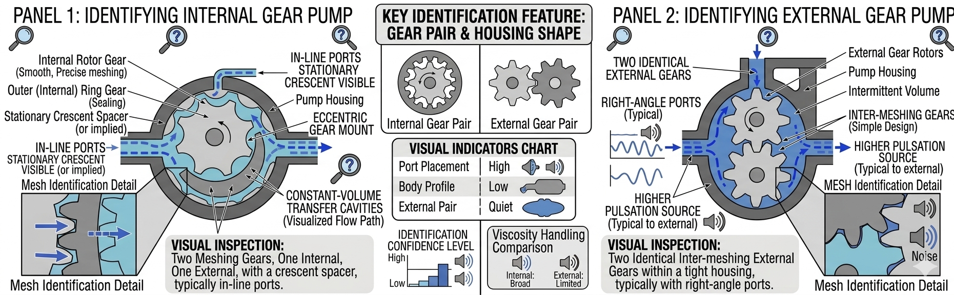
Identifying an unknown gear pump — whether from a dismantled machine, an unmarked replacement, or an inherited installation — is a common challenge in maintenance, procurement, and plant engineering. This guide covers every method for identifying the pump type (external vs internal), gear tooth profile, rotation direction, displacement, port connections, shaft size, seal arrangement, and material of construction — using only what is visible on the pump itself and its components. A full identification checklist is provided at the end.
| Identifying Feature | External Gear Pump | Internal Gear Pump |
|---|---|---|
| Number of shaft ports on casing | Two shaft ports (one for drive gear shaft, one for idler gear shaft) | One shaft port (drive shaft only; idler is supported internally on a pin or journal) |
| Casing shape | Typically rectangular or figure-8 cross-section — two circular bores side by side | Typically circular cross-section — one large bore for the outer ring gear |
| Gear arrangement (visible from port face) | Two identical gears of equal size side by side, meshing at the centre | One small gear (rotor/idler) eccentric inside a larger ring gear; crescent divider visible between them |
| Suction and discharge port position | Ports typically on same face, flanking the gear mesh zone | Ports typically on same face but offset to one side of the rotor centreline |
| Overall pump proportions | Often wider than tall — two shaft spans side by side | Often more compact and nearly circular in cross-section |
📖 Read More: Gear Pump Guide: How It Works, Types & How to Choose
| Gear Type | Visual Identification | Rotation Reversible? | Performance Notes |
|---|---|---|---|
| Spur gears | Straight teeth parallel to shaft axis — teeth appear as straight bars across the gear face | Yes — bi-directional | Higher flow pulsation; simpler to manufacture; lower cost |
| Single helical gears | Teeth are angled across the gear face — appear as diagonal lines when viewed from the end | No — rotation-direction-specific | Quieter than spur; generates axial thrust; UA Series standard design |
| Herringbone / double helical | Teeth form a V or chevron pattern across the gear face — two mirror-image helical patterns meeting at the gear centre | No — inherently directional | Quietest; eliminates axial thrust; highest cost; largest axial width |
| Gerotor (internal gear only) | Smooth lobed profile — rotor has N lobes, ring gear has N+1 lobes; no separate crescent seal | Yes — bi-directional | Very smooth flow; compact; limited to lower pressure than crescent design |
For external gear pumps: Displacement (cm³/rev) ≈ 2 × π × (Pitch Radius)² × (Gear Face Width) × Number of Teeth × Tooth Addendum. In practice for field identification, measure the gear OD, gear face width (axial length), and tooth depth — these three measurements with the tooth count allow an approximate displacement calculation.
| Port Size Identifier | Nominal Port Size | Typical Flow Range |
|---|---|---|
| G 3/8" BSP or 3/8" NPT | DN10 | 2–15 LPM |
| G 1/2" BSP or 1/2" NPT | DN15 | 5–30 LPM |
| G 3/4" BSP or 3/4" NPT | DN20 | 15–60 LPM |
| G 1" BSP or 1" NPT | DN25 | 30–150 LPM |
| G 1.5" BSP or 1.5" NPT | DN40 | 80–400 LPM |
| G 2" BSP or 2" NPT | DN50 | 200–800 LPM |
| G 3" BSP or 3" NPT | DN80 | 600–2500 LPM |
| G 4" BSP or 4" NPT | DN100 | 1500–6000 LPM |
| Pump Body Material | Visual Identification | Physical Test | Typical Application |
|---|---|---|---|
| Cast iron | Dark grey, slightly granular surface finish; magnetic | Magnetic; brittle if struck; heavier than equivalent steel pump | Standard duty — oils, non-corrosive fluids, hydraulic service |
| Mild steel / carbon steel | Silver-grey; may show rust staining; magnetic | Magnetic; smoother surface than cast iron; weld seams may be visible | Chemical and process applications; welded or fabricated bodies |
| Stainless steel (SS304 or SS316) | Bright or satin silver; non-magnetic (SS316) or weakly magnetic (SS304) | Non-magnetic test; resists strong acid; no rust in water | Food, pharmaceutical, chemical — corrosion-resistant service |
| Gun metal / bronze | Brownish-gold or greenish patina; non-magnetic | Non-magnetic; softer than steel; slightly flexible shavings | Marine, water supply, seawater — bronze alloy for corrosion and dezincification resistance |
| Aluminium | Light silver-grey; very light weight for size; non-magnetic | Very light; soft — scratches easily with steel; non-magnetic | Light-duty hydraulic, portable equipment, mobile service pumps |
| Identification Item | Your Finding | Notes |
|---|---|---|
| Pump type (external / internal) | ___ | From casing shape and shaft port count |
| Gear tooth profile | ___ | From gear face inspection |
| Rotation direction | ___ | From casing arrow, helix direction, or seal hand |
| Displacement (cm³/rev) | ___ | From nameplate, model number, or calculated |
| Rated maximum speed (RPM) | ___ | From nameplate |
| Rated maximum pressure | ___ | From nameplate |
| Shaft diameter (mm) | ___ | Measured with outside micrometer |
| Suction port size and connection type | ___ | Thread type and nominal size |
| Discharge port size and connection type | ___ | Thread type and nominal size |
| Seal arrangement type | ___ | Gland packing / mechanical seal / lip seal / sealless |
| Seal hand (RH / LH) if single coil spring | ___ | From spring winding direction |
| Body material | ___ | From visual inspection and magnetic test |
| Gear / shaft material | ___ | From colour, hardness test, magnetic test |
| Nameplate model number | ___ | Record all visible characters |
| Nameplate serial number | ___ | For manufacturer cross-reference |
📖 Read More: Gear Pump Installation Guide
Look at the number of shaft ports in the casing. External gear pumps have two shaft ports (one for the drive gear, one for the idler gear). Internal gear pumps have one shaft port (the idler gear is supported internally). The casing shape also differs — external pumps are typically rectangular or figure-8; internal pumps are typically circular.
Remove the front cover and measure the gear OD, face width (axial length), and tooth depth. Count the teeth. Use the approximate displacement formula or compare measurements against the manufacturer's standard size series. If the pump appears to be a UA Series pump, contact Unique Pump Systems with your measurements for cross-reference.
Measure the shaft diameter with an outside micrometer. Identify the seal hand from the spring winding direction. Identify the seal bore material. Then use these measurements with the datasheet template to order the correct replacement.
Unique Pump Systems manufactures rotary gear pumps in the UA Series across the full range of sizes, materials, and configurations. If you have an unidentified pump and need a cross-reference or replacement specification, contact our technical team with your measurements and photographs.