Unique Pump Systems, Kailash Industrial Complex, Vikhroli (W)
The short answer is that there are more than 20 distinct mechanical seal types when all classification axes are counted — and the number a procurement engineer, maintenance manager, or process designer encounters depends entirely on which classification system they are using. Most guides list 5 or 6 types and stop there, leaving engineers uncertain about where split seals, gas-lubricated seals, dry-running seals, and API-categorised seal arrangements fit into the picture. This guide covers the complete classification tree — seven independent classification axes, the specific seal type on each axis, the engineering reason each variant exists, and a master selection matrix that maps application conditions to the correct seal type. For the full range of mechanical seal options and specifications, including Type 41 and Type 42 DIN EN 12756-compliant seals in a wide range of face material and elastomer combinations, see the Unique Pump Systems product range.
Also Read: How to Replace a Mechanical Seal on a Water Pump
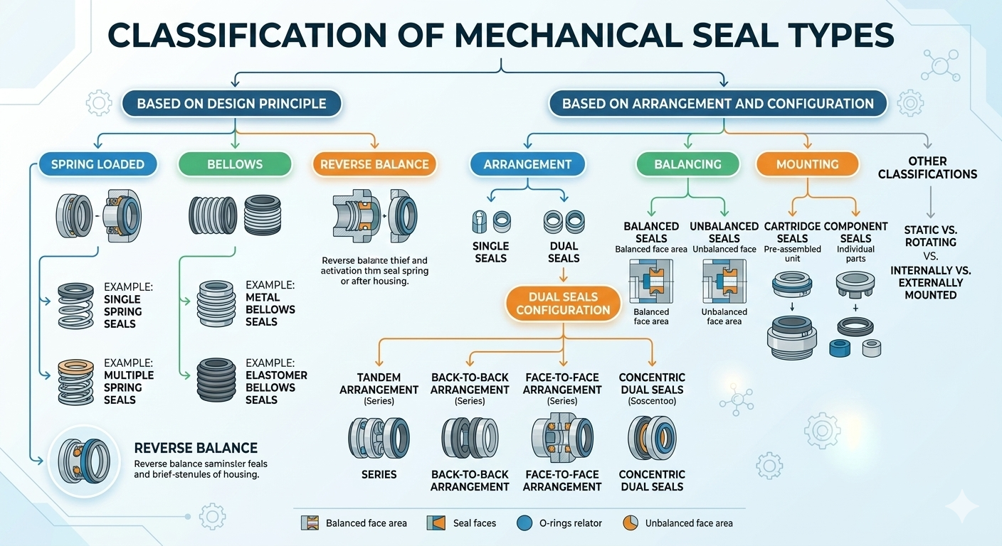
Mechanical seals are classified along seven independent axes. Each axis describes one specific aspect of the seal's design or arrangement. A complete seal specification requires a choice on each axis:
| Classification Axis | Types | What It Determines |
|---|---|---|
| 1. Hydraulic Balance | Balanced / Unbalanced | Maximum operating pressure capability |
| 2. Spring Mechanism | Pusher (spring-loaded) / Non-pusher (bellows) | Axial movement accommodation, temperature suitability |
| 3. Sealing Arrangement | Single / Double / Tandem | Hazardous fluid containment level |
| 4. Mounting Position | Inside-mounted / Outside-mounted | Fluid contact with spring, accessibility |
| 5. Assembly Format | Component (loose parts) / Cartridge (pre-assembled) | Installation risk, maintenance complexity |
| 6. Rotational Element | Rotating face / Stationary face | Suitability for large shaft diameters, high speeds |
| 7. Lubrication Regime | Liquid-lubricated / Gas-lubricated / Dry-running | Gas sealing, high-speed, clean-room applications |
Hydraulic balance describes how much of the pump's fluid pressure acts on the seal face in the closing direction. It is expressed as the balance ratio (B) — the ratio of the hydraulically loaded face area to the total face area.
In an unbalanced seal, the full hydraulic pressure of the pumped fluid acts over the entire back face of the rotating seal ring, pushing it toward the stationary seat. This creates a high closing force — which produces tight sealing but also high face contact pressure, high frictional heat at the seal interface, and accelerated face wear.
A balanced seal reduces the hydraulic closing force by relieving a portion of the fluid pressure from the seal face area. This is achieved by creating a step or relief in the shaft sleeve or seal ring, so that a portion of the back face area is exposed to a lower (typically atmospheric) pressure rather than full process pressure.
The spring mechanism maintains closing force between the seal faces as the faces wear over time. Two fundamentally different approaches achieve this:
Pusher seals use one or more springs (single coil spring, multiple coil springs, or wave springs) to push the rotating seal ring axially toward the stationary seat. As the seal faces wear, the springs allow the rotating ring to move axially to maintain face contact — this axial movement is what 'pushes' the secondary seal (O-ring or V-ring) along the shaft sleeve.
The key limitation of pusher seals: the secondary O-ring or V-ring must slide along the shaft sleeve to accommodate axial movement. This sliding action causes fretting wear on the shaft sleeve and can stick (hang up) in corrosive or dirty service, preventing the seal from following face wear and causing it to lose face contact.
Non-pusher seals replace the spring and sliding secondary seal with a flexible bellows element. The bellows acts simultaneously as the spring (providing closing force), the secondary seal (preventing leakage along the shaft), and the axial compensator (allowing face wear tracking) — all without any sliding motion on the shaft sleeve.
Bellows seals are preferred in: high-temperature applications (hot oil, thermal fluid systems), cryogenic service (liquefied gases), applications where shaft sleeve fretting is a chronic problem, and wherever rotation-independent operation is needed (pumps that may run in either direction).
The sealing arrangement describes how many mechanical seals are installed and how they are oriented relative to each other and the pumped fluid.
A single mechanical seal consists of one rotating face and one stationary seat. It is the standard configuration for the majority of industrial pump applications where the fluid is not hazardous or toxic, and where a controlled level of leakage to atmosphere is acceptable (the microscopic vapour leakage inherent in all mechanical seals).
A double mechanical seal consists of two complete seal assemblies installed in the same seal chamber, with a barrier fluid system between them. The two seals are oriented back-to-back (most common) or face-to-face. The barrier fluid fills the space between the two seals and is maintained at a pressure above the process fluid pressure.
How it works: the inner seal (process side) prevents process fluid from reaching the barrier fluid space. The outer seal (atmosphere side) prevents barrier fluid from leaking to atmosphere. Because barrier fluid pressure is higher than process pressure, any leakage at the inner seal face is barrier fluid migrating inward into the process — not process fluid leaking outward. This means zero hazardous fluid reaches the atmosphere, regardless of inner seal condition.
A tandem seal consists of two seals oriented in the same direction (both facing the process side), with a buffer fluid system between them. Unlike the double seal's pressurised barrier, the tandem configuration uses a buffer fluid maintained at a pressure below process pressure.
How it works: the primary (inner) seal carries the full process pressure differential. The secondary (outer) seal serves as a backup — it is not loaded under normal operation. If the primary seal fails, the secondary seal contains the leakage until the pump can be shut down for maintenance. The buffer fluid space allows detection of primary seal failure through level or flow monitoring before the process fluid reaches the atmosphere.
The vast majority of industrial pump mechanical seals are inside-mounted — the rotating face is installed inside the pump's stuffing box or seal chamber, with the spring and secondary seal elements immersed in or in contact with the process fluid. The fluid provides lubrication to the spring and secondary seal.
An outside-mounted seal positions the spring and secondary seal elements outside the seal chamber — in air rather than in contact with the process fluid. Only the seal faces and their immediate holders are exposed to the process.
A component seal is supplied as individual parts — rotating face, stationary seat, spring(s), drive collar, O-rings, and gland plate — which are assembled onto the shaft in the correct sequence during installation. The assembler must set the spring compression length by measuring the working length and positioning the drive collar set screws at the correct position on the shaft.
A cartridge seal is a pre-assembled, self-contained unit — all components (rotating face, stationary seat, spring, drive collar, gland plate, and secondary seals) are factory-assembled onto a sleeve that fits over the shaft as a complete unit. The spring compression is factory-set using gauging tabs or clips that are removed after installation but before final tightening.
In a standard mechanical seal, the harder, more wear-resistant face (typically silicon carbide or tungsten carbide) rotates with the shaft, while the softer, self-lubricating face (typically carbon-graphite) is stationary. However, this arrangement can be reversed.
The vast majority of mechanical seals in industrial process pumps are liquid-lubricated — the fluid being pumped (or a clean barrier/flush fluid) forms the thin fluid film between the seal faces that provides lubrication and prevents the faces from running in dry contact. The seal design, face flatness, and surface roughness are all optimised around the formation and stability of this liquid film.
Gas-lubricated mechanical seals — commonly called dry gas seals (DGS) — are used in gas compressors, high-speed pumps handling near-vapour-pressure fluids, and any application where a liquid fluid film between the faces is not available or not desirable. Instead of a liquid film, the seal faces are designed with spiral grooves or other hydrodynamic features that generate a gas film under rotation, keeping the faces slightly separated on a very thin (typically 3–5 micron) gas cushion.
Dry-running seals are designed to operate without any fluid film between the faces for extended periods — used in applications where no liquid is available for lubrication (dry powder handling, vacuum systems, some gas handling applications). They use special hard face material combinations (typically SiC against SiC, or carbon against SiC with special graphite grades) and rely on the self-lubricating properties of one face material rather than an external fluid film.
The choice of face material pair is independent of the seal type classification above but equally critical to seal life and chemical compatibility.
| Face Pair | Rotating / Stationary | Best Application | Avoid With | Relative Cost |
|---|---|---|---|---|
| Carbon / Ceramic | Carbon rotates / Ceramic stationary | Clean water, light chemicals, low-pressure general service | Abrasive slurries, hydrofluoric acid (attacks ceramic) | Low |
| Carbon / Silicon Carbide (SiC) | Carbon rotates / SiC stationary | Standard industrial — most chemicals, water, oils, mild acids and alkalis | Hydrofluoric acid, strong caustic above 50°C (attacks carbon in some grades) | Medium |
| SiC / SiC (Reaction-Bonded) | Both faces SiC | Abrasive slurries, abrasive chemicals, aggressive service where carbon would erode | Hydrofluoric acid (attacks SiC) | Medium-High |
| Tungsten Carbide / Tungsten Carbide (TC/TC) | Both faces TC | Highly abrasive fluids, high-pressure service, fluids that attack SiC | Some chemical environments — verify compatibility; TC is not universally resistant | High |
| Carbon / Tungsten Carbide | Carbon rotates / TC stationary | Moderate abrasion with softer fluid phase; where TC seat hardness is needed but SiC is unavailable | Strong oxidising acids (may attack TC binder phase) | Medium-High |
| Alumina Ceramic / Carbon | Ceramic stationary / Carbon rotates | Light duty, cost-sensitive applications with clean non-abrasive fluids | Abrasive or shock loading (ceramic is brittle) | Low |
Secondary seals prevent leakage at the interfaces between the rotating seal ring and the shaft, and between the stationary seat and the gland plate. They are static seals (not face-to-face dynamic seals) but their material and design are critical to seal performance.
| Secondary Seal Type | Design | Advantages | Limitations | Typical Use |
|---|---|---|---|---|
| O-Ring (Type 41) | Circular cross-section elastomeric ring in a groove | Simple, low cost, effective static seal, wide material availability (NBR, Viton, EPDM, PTFE) | Elastomer must be compatible with fluid; O-ring can stick (hang up) in abrasive or sticky fluids, preventing axial movement | Standard for most general industrial applications |
| V-Packing / TTV Packing (Type 42) | PTFE-based chevron-profile ring | Excellent chemical resistance (PTFE compatible with almost all chemicals), universal compatibility seal | Higher friction than O-ring; less sensitive spring force available for face tracking; requires correct installation load | Aggressive chemicals that would attack standard elastomers |
| Wedge Ring | Angled elastomeric profile that wedges against shaft sleeve as pressure increases | Self-energising — sealing force increases with pressure; no hang-up risk | Not suitable for low-pressure or vacuum service where the wedging action is not activated | Higher pressure applications, large bore seals |
| Elastomeric Bellows | Moulded elastomeric component acting as both spring and secondary seal | No shaft sleeve contact or fretting; rotation-independent; no O-ring hang-up | Limited temperature range vs metal bellows; elastomer must be compatible with fluid | Low-to-medium temperature chemical service, pumps with bi-directional rotation |
| Metal Bellows | Thin corrugated metal component acting as both spring and secondary seal | No elastomer in dynamic zone — compatible with extreme temperatures and aggressive chemicals; no O-ring hang-up | Higher cost; metal fatigue limit must not be exceeded by over-compression or excessive shaft runout | High temperature (hot oil, thermal fluid), cryogenic, highly corrosive services |
For pumps in the oil and gas, petrochemical, and refining industries, the API 682 standard defines a structured framework for mechanical seal selection and the associated seal support (flush) systems. Understanding this standard is essential for specifying seals in regulated industries.
| Category | Seal Type | Typical Application |
|---|---|---|
| Category 1 | Inside-mounted, single or dual seals with non-contacting or contacting faces; unbalanced or balanced depending on pressure | General refinery and chemical plant service — light-end hydrocarbons, water, mild process fluids |
| Category 2 | Cartridge-mounted, single or dual seals; balanced; pusher or bellows | More demanding refinery service — medium hydrocarbons, moderate temperatures, higher pressures |
| Category 3 | Cartridge-mounted, dual seals (pressurised barrier); balanced; metal bellows standard | Severe service — highly toxic, carcinogenic, or environmentally regulated fluids; zero emission to atmosphere required |
Seal support piping plans define how flush fluid is supplied to and circulated around the seal faces to maintain the fluid film, control temperature, and manage contamination. Selecting the correct plan is as important as selecting the correct seal type.
| API Plan | Description | When to Use |
|---|---|---|
| Plan 11 | Flush from pump discharge through orifice to seal — simple internal recirculation | Clean, non-flashing fluids where process fluid is acceptable as flush. Most common plan for general service. |
| Plan 13 | Flush from seal back to pump suction — creates flow through seal from suction side | Used when Plan 11 creates too high a differential pressure across the seal, or for vertical pumps |
| Plan 21 | Flush from pump discharge through heat exchanger (cooler) to seal | Hot fluids where the process fluid temperature would cause vapour flashing or excessive heat at the seal faces |
| Plan 23 | Pumping ring circulates fluid from seal chamber through seal-mounted heat exchanger and back — independent of pump internals | Hot water and boiler feed water service — seals that would otherwise see near-boiling fluid and flash |
| Plan 32 | External clean fluid injected into seal chamber from an external source | Slurry or abrasive fluid service where the process fluid must be excluded from the seal faces completely |
| Plan 52 | Buffer fluid reservoir (unpressurised) for tandem seal — buffer fluid circulates between inner and outer seals by convection or pumping ring | Tandem seals in light hydrocarbon or moderate chemical service; allows detection of inner seal failure through buffer fluid monitoring |
| Plan 53A | Pressurised barrier fluid reservoir for dual seal — reservoir pressurised with nitrogen above process pressure | Double seals in hazardous fluid service where zero process fluid leakage to atmosphere is required |
| Plan 54 | Pressurised barrier fluid supplied from central system — pump circulates barrier through seals | Large dual-seal installations where central barrier fluid management is more economical than individual seal pots |
Use this matrix to identify the correct seal type for your application conditions. Start with the most constraining parameter (usually fluid hazard level or pressure) and work across.
| Application Condition | Recommended Seal Type | Key Specification Points |
|---|---|---|
| Clean water, low pressure (<8 bar), general utility | Single / Unbalanced / Pusher (single spring) / Component | Carbon/ceramic faces; NBR or EPDM O-rings; Type 41 DIN EN 12756 |
| Chemical service, moderate pressure (8–25 bar) | Single / Balanced / Pusher (multiple spring) or Bellows / Component or Cartridge | Carbon/SiC faces; Viton or PTFE secondary seals; verify chemical compatibility |
| High pressure (>25 bar), any fluid | Single / Balanced / Pusher / Cartridge recommended | SiC/SiC or TC/TC faces for pressure capability; multiple spring design for uniform face loading |
| Abrasive slurry or particle-laden fluid | Single / Balanced / Outside-mounted or Plan 32 flush / Cartridge | SiC/SiC or TC/TC faces; outside mounting to keep spring out of fluid; Plan 32 flush to exclude slurry from faces |
| Highly corrosive chemical (strong acid/alkali) | Single / Balanced / Metal bellows (non-pusher) / Component or Cartridge | SiC/SiC faces; metal bellows eliminates elastomer from dynamic zone; Hastelloy spring/bellows material |
| Toxic, hazardous, or zero-emission required | Double / Balanced / Cartridge (API Arrangement 3) / Plan 53A | Pressurised barrier fluid at >1 bar above process pressure; continuous barrier level monitoring |
| Backup protection, planned shutdown margin | Tandem / Balanced / Cartridge (API Arrangement 2) / Plan 52 | Unpressurised buffer fluid; inner seal at full process pressure; secondary seal as backup |
| High temperature (>150°C) hot oil or thermal fluid | Single / Balanced / Metal bellows / Cartridge | Metal bellows eliminates elastomer temperature limit; SiC/SiC or carbon/SiC with high-temp grades; Plan 21 or 23 cooling |
| Cryogenic service (liquefied gases, <-50°C)< /strong> | Single / Balanced / Metal bellows / Cartridge | Metal bellows; SiC/SiC faces; Hastelloy construction; carefully managed flush plan to prevent ice formation |
| Large shaft diameter (>100 mm) or high speed | Single / Balanced / Stationary face design / Cartridge | Stationary face eliminates centrifugal spring force issues; cartridge format for dimensional accuracy at large bore |
| Food grade / pharmaceutical / hygienic | Single / Balanced / Elastomeric bellows or component / FDA-compliant materials | 316L SS metal parts; FDA/USP-compliant elastomers; SiC/SiC or carbon/SiC faces; CIP/SIP-compatible design |
| Bi-directional shaft rotation (pump reversal possible) | Single / Balanced / Non-pusher (bellows) / Any format | Bellows design is rotation-independent; single coil spring seals must be specified for correct hand per rotation direction |
Different seal types fail in different ways. Understanding the failure mode helps maintenance teams identify the root cause from physical evidence on removed seals.
| Seal Type | Characteristic Failure Mode | Physical Evidence | Root Cause Investigation |
|---|---|---|---|
| Unbalanced seal at elevated pressure | Face heat cracking — circular crack pattern in ceramic or carbon face | Concentric cracks or blistering on face; carbon face may show coking | Pressure exceeding seal's balance ratio capability; check if balanced seal is required |
| Pusher seal — O-ring hang-up | Faces open under axial shaft movement; sudden heavy leakage after previously normal operation | O-ring shows groove wear or is stuck in shaft sleeve groove; spring fully compressed | Abrasive or sticky fluid packing into O-ring groove; switch to bellows or outside-mounted design |
| Single coil spring — wrong rotation | Rapid spring fatigue; spring unwinds and collapses | Spring elongated or broken; drive collar loose on shaft; seal loses face contact quickly | Spring rotation direction does not match shaft rotation; replace with correct hand |
| Cartridge seal — gauging clips not removed | Zero face contact from installation; immediate leakage from first start | Faces never show wear track; gauging clips found in situ or nearby | Operator missed clip removal step; add to installation checklist/signoff |
| Double seal — barrier fluid loss | Inner seal failure allows process fluid into barrier space; outer seal overloaded and fails | Process fluid found in barrier fluid reservoir; outer seal shows rapid wear | Inner seal failure not detected (no alarm on barrier level drop); fit automated monitoring |
| Metal bellows — fatigue fracture | Sudden large leakage; bellows visibly cracked or perforated | Crack in bellows corrugations; fluid contamination of air side | Excessive shaft runout, over-compression during installation, or bellows operating beyond fatigue limit |
| SiC face — thermal shock fracture | Crescent or radial crack in SiC face from rapid temperature change | Visible crack from face edge; SiC fragments may be found in pump | Rapid startup without pre-warming, or cold flush fluid injected onto hot face; thermal soak protocol needed |
Unique Pump Systems supplies mechanical seal solutions for a wide range of industrial pump applications — including Type 41 (O-ring type) and Type 42 (V-packing type) single coil spring seals to DIN EN 12756 standard, in shaft diameters from 10 mm to 100 mm, with face materials in carbon, silicon carbide, and tungsten carbide, and elastomers in NBR, Viton, PTFE, EPDM, and GFT. For complex applications requiring balanced seals, cartridge designs, double seal arrangements, or specific material specifications for hazardous or aggressive fluids, contact our technical team for a selection recommendation matched to your pressure, temperature, fluid chemistry, and shaft configuration.
Mechanical seals are classified on seven independent axes: hydraulic balance (balanced/unbalanced), spring mechanism (pusher/non-pusher bellows), sealing arrangement (single/double/tandem), mounting position (inside/outside), assembly format (component/cartridge), rotational element (rotating face/stationary face), and lubrication regime (liquid/gas/dry). Counting each distinct combination gives well over 20 meaningfully different seal configurations — which is why the simple answer of '6 types' understates what engineers need to know.
For practical selection: start with the sealing arrangement (determined by fluid hazard level), then determine the balance requirement (pressure and fluid lubricity), then the spring type (temperature and shaft movement requirements), then the face material pair (chemical compatibility and abrasion resistance), and finally the secondary seal material (fluid compatibility). For regulated industries, align the complete specification to the appropriate API 682 category and seal support piping plan.