Unique Pump Systems, Kailash Industrial Complex, Vikhroli (W)
An internal gear pump is a specific type of gear pump that uses two gears of different sizes — one rotating inside the other — to move fluid through a system. While it shares the positive displacement principle with all gear pumps, the internal gear configuration gives it a fundamentally different set of capabilities: the ability to handle extremely viscous, shear-sensitive, temperature-sensitive, and high-solid-content fluids that would quickly wear out or underperform in an external gear pump.
This guide focuses entirely on the internal gear pump — its unique anatomy, the physics behind its working principle, the design variants you will encounter (crescent vs. gerotor), the model series used in hydraulic applications, the specific industries that rely on it, and how to select and maintain one correctly. If you are trying to decide whether an internal or external gear pump is right for your application, this guide gives you the technical depth to make that call with confidence.
Read More: Gear Pump Guide
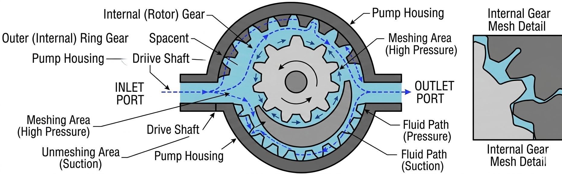
The defining structural feature of an internal gear pump is its eccentric gear arrangement. Unlike an external gear pump where two identical gears sit side by side, an internal gear pump positions a smaller external gear (the rotor) inside a larger internal gear (the idler or ring gear). These two gears rotate on different axes — the rotor axis is offset from the idler axis. This eccentric offset is what creates the expanding and collapsing fluid chambers that drive pumping action.
The rotor is the smaller of the two gears and is the driven element — connected directly to the motor shaft. It has external teeth on its outer circumference. The rotor sits off-centre inside the idler gear and its teeth mesh with the idler at one point in each revolution. The number of teeth on the rotor is always one fewer than the number of teeth on the idler — this difference in tooth count is what creates the relative rotational motion between the two gears as the rotor drives the idler.
The idler is the larger gear with internal teeth cut on its inner surface. It floats freely inside the pump casing — it is not shaft-mounted. The idler is driven entirely by the rotor through tooth engagement. Because the idler has one more tooth than the rotor, it rotates at a slightly slower angular speed. This speed difference between the two gears, combined with the eccentric offset, is what creates the continuously changing cavity volumes that produce fluid flow.
In the most common internal gear pump design, a fixed, crescent-shaped seal is installed in the space between the rotor and the idler where the gears are furthest apart. The crescent does not rotate. Its purpose is to separate the suction zone (where cavities are expanding and fluid is being drawn in) from the discharge zone (where cavities are collapsing and fluid is being pushed out). Without the crescent, fluid could simply flow back from the high-pressure side to the low-pressure side along the widest gap between the gears.
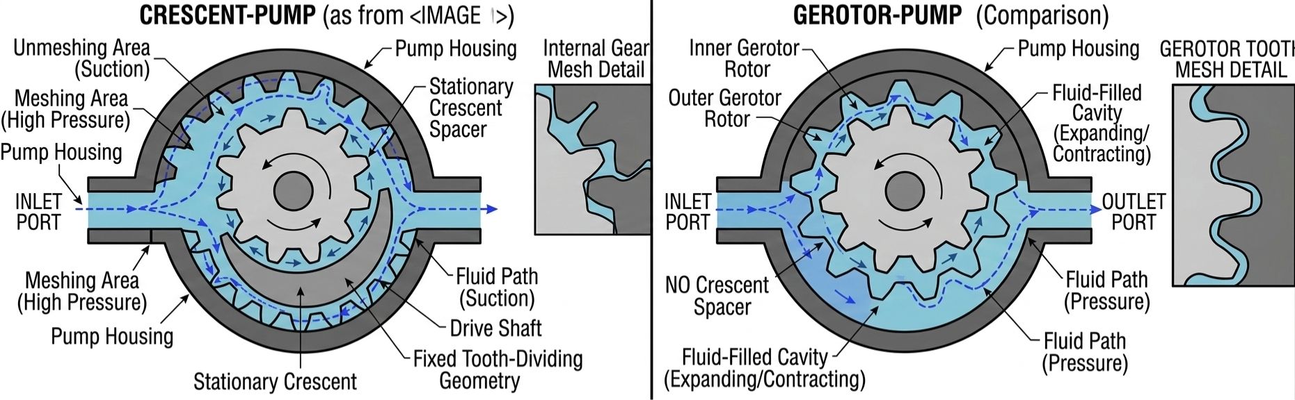
The gerotor (generated rotor) is an alternative internal gear pump design that eliminates the crescent seal entirely. In a gerotor, the tooth profile of the rotor and idler are precisely engineered so that the gears maintain a continuous seal contact around their entire circumference. At every point in the rotation, the gear teeth contact the mating gear surface — there is no gap requiring a crescent to fill.
The gerotor design is more compact and has fewer parts, but it achieves sealing through geometry rather than a physical separator. This makes gerotors well suited for lower-pressure, high-speed applications (engine oil pumps, automotive transmission pumps) where absolute pressure sealing is less critical and compactness matters most. For industrial process pumps handling viscous fluids at higher pressures, the traditional crescent design remains the dominant choice.
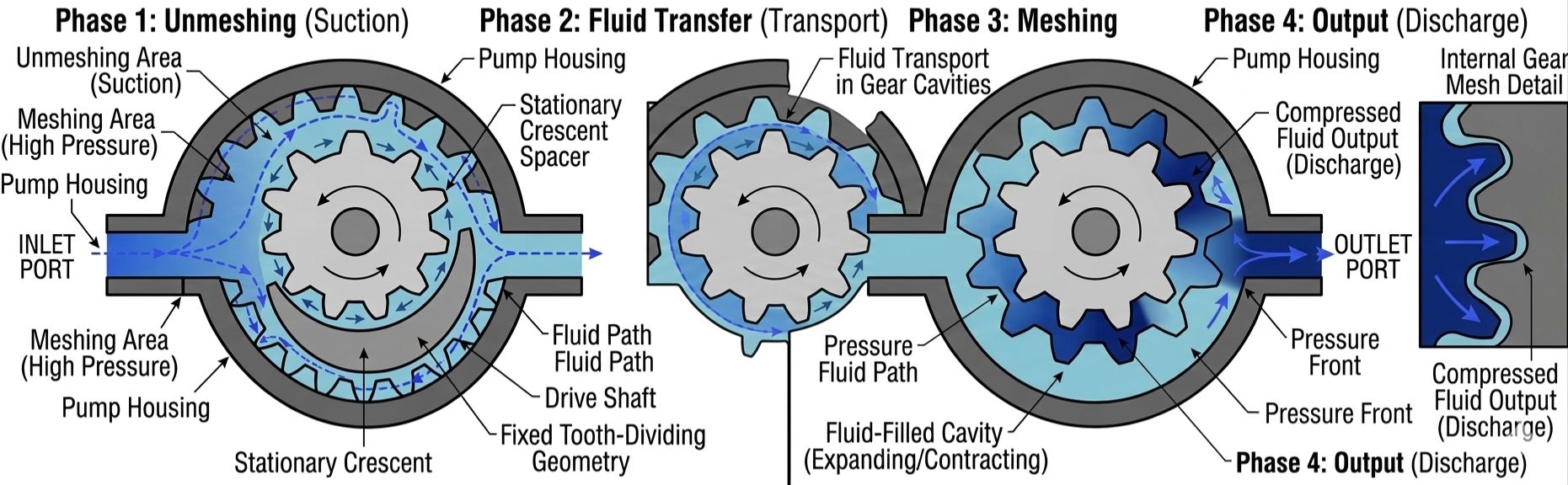
The working principle of an internal gear pump can be followed through four distinct phases in every revolution of the rotor:
As the rotor rotates and drives the idler, the teeth of both gears disengage on the side opposite to where they mesh. As the teeth pull apart in this region, the volume of the space between them rapidly increases — forming an expanding cavity. This expanding cavity creates a localised low-pressure zone. Because the pump inlet port is positioned at exactly this location, atmospheric pressure (or the head pressure of the fluid in the feed tank) pushes fluid into the cavity to fill the void. The fluid has entered the pump.
The fluid trapped in the cavity between rotor teeth, the crescent seal surface, and the idler inner surface is now physically carried around the pump as the gears rotate. On the rotor side of the crescent, fluid occupies the cavities between adjacent rotor teeth and the crescent's outer curved surface. On the idler side, fluid fills the cavities between the idler's inner teeth and the crescent's inner curved surface. The crescent acts as a dividing wall — preventing fluid from passing directly from the discharge side back to the suction side.
As the rotor and idler teeth approach the meshing point on the other side of the pump, the cavities shrink. The gear teeth begin to interlock — the rotor tooth enters the space between two idler teeth, progressively reducing the available volume. The fluid in the collapsing cavity has nowhere to go except through the discharge port. It exits the pump under pressure. The pressure developed is determined by the resistance of the downstream system — the pump generates the flow; the system generates the pressure.
Because there are multiple tooth cavities filling and discharging simultaneously at different angular positions, the flow from an internal gear pump is exceptionally smooth — far smoother than a reciprocating pump and noticeably smoother than a typical external gear pump. The overlapping phase transitions between cavities result in very low pressure pulsation, which is one of the defining advantages of the internal gear pump design for sensitive fluid applications.
Design insight: The smoothness of flow from an internal gear pump is a direct result of the large number of teeth in simultaneous engagement at any point in the rotation. More teeth in contact = more cavities transitioning between phases simultaneously = lower pressure pulsation amplitude.
Also Read: Gear Pump Installation
This is one of the most important technical distinctions between internal and external gear pumps, and it is worth understanding at a deeper level than simply 'internal pumps handle thick fluids better.'
In an external gear pump, the two gears mesh at the centre of the pump. The suction port is on one side of the mesh point. To draw viscous fluid into the pump, the fluid must travel from the inlet, around the outside of both gears, and into the tooth cavities — a relatively long, narrow path.
In an internal gear pump, the large idler gear surrounds the rotor. The inlet port can be positioned much closer to the expanding cavities and the path from inlet to cavity is shorter and wider. For a thick fluid that resists flowing quickly, this shorter, more open suction path means the fluid can fill the cavities more completely at a given RPM — resulting in better volumetric efficiency at high viscosity.
External gear pumps require very tight clearances between gear faces and side plates to maintain efficiency — typically in the range of 5–25 microns. This tightness is what gives them their high-pressure capability and precision, but it also means that very viscous fluids create significant viscous drag as they are sheared through these narrow gaps, generating heat and increasing required drive torque.
Internal gear pumps have inherently more relaxed clearances because the crescent seal and the geometry of the idler provide the sealing function rather than ultra-tight face clearances alone. This means less viscous shear, lower heat generation, and the ability to handle fluids up to 100,000 cSt or beyond without excessive power consumption or fluid degradation.
Many industrial fluids — polymers, adhesives, certain food products, biological fluids, non-Newtonian fluids — are shear-sensitive: their viscosity changes (often permanently) when subjected to high shear forces. In an external gear pump, the tight clearances and the meshing action between two external gear faces create high shear zones. In an internal gear pump, the meshing occurs between the rotor's external teeth and the idler's internal teeth in a rolling action — generating significantly lower shear. For shear-sensitive fluids, this distinction is often the primary reason the internal gear pump is specified.
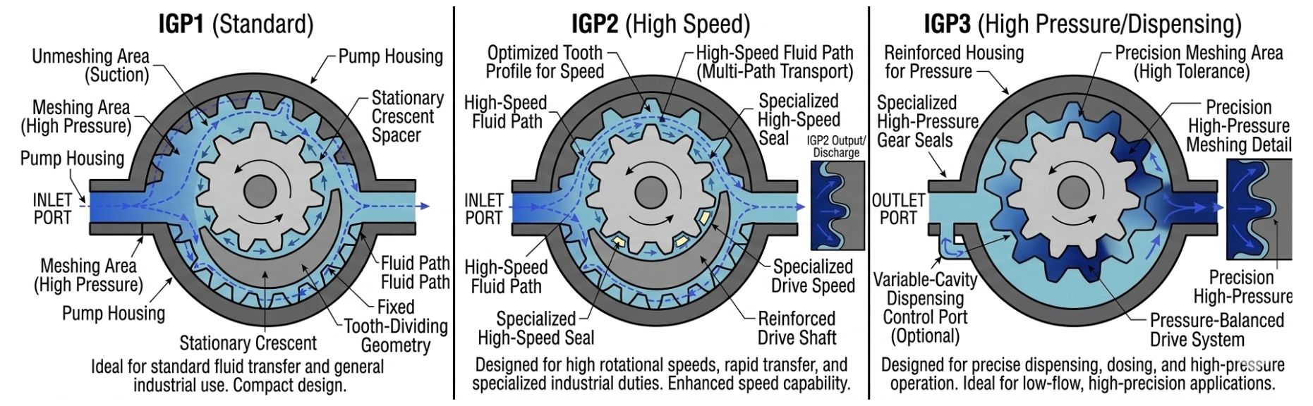
Internal gear pumps are available in a range of sizes and pressure ratings, often designated in model series based on displacement and duty level. The most widely referenced classification in industrial and hydraulic applications is the IGP series:
| Model Series | Duty Class | Typical Displacement Range | Typical Pressure Rating | Common Use Cases |
|---|---|---|---|---|
| IGP1 | Light to Medium Duty | 2 – 16 cc/rev | Up to 175 bar | Small hydraulic systems, lubrication circuits, light chemical transfer |
| IGP2 | Medium to Heavy Duty | 16 – 50 cc/rev | Up to 210 bar | Industrial hydraulics, fuel oil transfer, moderate viscosity process fluids |
| IGP3 | Heavy Duty / High Flow | 50 – 200+ cc/rev | Up to 250 bar | High-flow hydraulic circuits, heavy viscous fluid transfer, bitumen and resin systems |
Within each series, pumps are further specified by:
Internal gear pumps can operate in either direction of rotation and will pump fluid in either direction — reversing the motor reverses the flow direction. This is not true of most external gear pumps, where suction and discharge ports are fixed relative to rotation direction.
This bi-directional capability is valuable in several real applications:
Note: When specifying a bi-directional internal gear pump, confirm with the manufacturer that the shaft seal and port configuration are symmetrical — some designs have directionally optimised features that limit true bidirectionality at higher pressures.
Thermal oil systems, bitumen transfer, molten polymer lines, hot adhesive dispensing, and steam-traced process lines all share a common challenge: the fluid is hot, and the pump must maintain tight internal tolerances despite significant thermal expansion of metal components.
This is where the internal gear pump's relaxed internal clearances become a critical engineering advantage. In an external gear pump with very tight face clearances, thermal expansion of the gear faces and side plates can reduce the running clearance to near zero — causing the gears to make contact, generating heat, increasing wear, and ultimately seizing the pump.
In an internal gear pump, the inherently wider running clearances provide a thermal expansion buffer. As the pump heats up in service, the components expand — but there is sufficient clearance that the gears continue to rotate freely without contact. The practical result:
In the viscous fluid handling segment, the internal gear pump and the lobe pump are the two most commonly compared options. Both handle high-viscosity fluids, both have low shear, and both are positive displacement — but they have distinctly different strengths.
| Factor | Internal Gear Pump | Lobe Pump |
|---|---|---|
| Maximum Viscosity | Up to 100,000 cSt and beyond | Up to 1,000,000 cSt (better for very thick fluids) |
| Pressure Capability | Up to 200–250 bar | Typically 15–25 bar (low pressure) |
| Shear Sensitivity | Low shear — good for sensitive fluids | Very low shear — better for delicate solids-containing fluids |
| Solids Handling | Limited — tight enough to damage soft solids | Excellent — large open cavities, can pass soft solids |
| Hygiene / CIP | Possible with stainless, but complex disassembly | Industry standard for food, pharma (easy strip-down) |
| Flow Smoothness | Very smooth, low pulsation | Moderate pulsation (sinusoidal with lobe count) |
| Size / Cost | Compact, cost-effective | Larger, higher initial cost |
| Typical Applications | Oils, chemicals, bitumen, resins, thermal fluids | Food, pharma, cosmetics, fluids with suspended solids |
The guidance is straightforward: if your fluid is viscous but relatively clean and you need pressure capability, an internal gear pump is usually the better choice. If your fluid contains soft solids, requires hygienic design, or is extremely viscous (over 100,000 cSt), evaluate a lobe pump.
The shaft seal is the most maintenance-sensitive component of an internal gear pump. The seal type determines chemical compatibility, maximum operating temperature, acceptable shaft speed, and — critically — whether any leakage to atmosphere is acceptable.
A mechanical seal uses two precision-lapped surfaces — one rotating with the shaft, one stationary — pressed together by a spring to form a near-zero-leakage barrier. Mechanical seals are the standard for industrial chemical and process fluid applications. They are available in a wide range of face materials (carbon/silicon carbide, tungsten carbide) and elastomer types (NBR, Viton, PTFE, EPDM) to match specific fluid chemistry and temperature.
A lip seal (radial shaft seal) is a simple elastomeric ring that rides on the rotating shaft. It is lower cost, easier to replace, and adequate for lower pressures and moderate temperatures. However, lip seals have a finite leakage rate and are not suitable for toxic, hazardous, or food-grade fluids where zero leakage is required.
In applications handling toxic chemicals, carcinogenic fluids, aggressive solvents, or fluids where any external leakage is unacceptable, the internal gear pump can be supplied in a magnetically coupled sealless configuration. The motor drives the pump rotor through a magnetic coupling across a containment shell — there is no shaft penetration through the pump casing, and therefore no shaft seal. Leakage to atmosphere is physically impossible under normal operating conditions. Sealless internal gear pumps carry a cost premium but are the specification of choice in chemical, pharmaceutical, and semiconductor manufacturing environments.
The internal gear pump is most at home wherever the fluid is challenging — high viscosity, high temperature, shear sensitivity, or hazardous chemistry. Here is how it is applied across key industries:
Bitumen is one of the most demanding fluids in industrial pumping — high viscosity (often requiring the fluid to be preheated to 150–180°C to make it pumpable at all), abrasive particles in some grades, and extreme stickiness. Internal gear pumps with steam-jacketed casings, hardened gear materials, and high-temperature Viton seals are standard for bitumen loading/unloading terminals, asphalt plants, and refinery residue transfer. The pump casing is jacketed so that steam or hot water circulates around the pump body, maintaining fluid temperature and preventing solidification during standby periods.
Polymer processing lines — for polyurethane, epoxy, PVC plastisol, hot melt adhesives, and similar materials — use internal gear pumps for their low-shear, high-viscosity capability and their resistance to the abrasive filler particles often present in these materials. In hot melt adhesive systems, the pump must handle fluids at 150–200°C continuously while maintaining accurate metering — a role internal gear pumps fill well.
Food-grade internal gear pumps in 316 stainless steel with food-safe seal materials handle vegetable oils, glucose syrups, chocolate, caramel, margarine, and similar viscous food products. The low-shear characteristic is particularly important for chocolate and cream emulsions, which can be permanently damaged by high-shear pumping. Sealless magnetic drive versions are often specified where product purity is paramount.
Thermal oil circulation systems — used to supply process heat in rubber vulcanisation, food processing, chemical reactors, and wood drying — operate at fluid temperatures of 150–300°C or higher. Internal gear pumps, with their thermal expansion tolerance, high-temperature seal options, and compatibility with synthetic heat transfer fluids (Therminol, Dowtherm), are the standard circulation pump for these systems.
Accurate, repeatable chemical dosing requires a pump whose flow is precisely proportional to shaft speed with minimal variation. The internal gear pump delivers flow consistency and metering accuracy that matches external gear pumps, but with better performance on higher-viscosity chemical streams and the option of sealless design for toxic or pharmaceutical-grade fluids.
In hydraulic applications, internal gear pumps are used where low noise, smooth flow, and high-viscosity fluid compatibility are priorities — for example, in precision hydraulic presses, hydraulic power units for paper and printing machinery, and systems using fire-resistant hydraulic fluids (which tend to have different viscosity characteristics than standard mineral oil). The IGP1, IGP2, and IGP3 series cover the range from small hydraulic power units to high-flow industrial hydraulic systems.
Use this checklist when specifying an internal gear pump for a new application:
| Parameter | What to Determine | Why It Matters |
|---|---|---|
| Fluid viscosity | At minimum and maximum operating temperature | Determines pump size (cc/rev) and operating speed range |
| Flow rate required | LPM at operating conditions | Drives displacement and RPM selection |
| System pressure | Maximum continuous + peak pressure | Confirms pressure rating of selected model series (IGP1/2/3) |
| Fluid temperature | Min (cold start) and max (steady state) | Determines seal material, casing option (jacketed?), and material grade |
| Fluid chemistry | pH, solvent content, oxidising/reducing agents | Determines wetted material — cast iron, SS316, bronze, special alloys |
| Shear sensitivity | Does viscosity change with shear? | If yes, confirms internal gear pump over external; may rule out lobe pump too |
| Solids content | Particle size, hardness, concentration | Hard particles → hardened gear option; soft large particles → consider lobe pump instead |
| Leakage tolerance | Can any fluid reach atmosphere? | If no → magnetically coupled sealless design required |
| Drive configuration | Motor RPM, shaft type, mounting standard | Drives shaft/coupling/mount selection — must match motor IEC/NEMA frame |
| Suction conditions | Inlet elevation, pipe size, strainer presence | Ensures pump receives adequate flow — prevents cavitation at startup |
Internal gear pumps are low-maintenance by design — fewer moving parts than a piston pump, no valves, no reciprocating components. But the following factors warrant regular attention:
As the pump wears, the running clearances between rotor, idler, crescent, and side plates increase. This increased clearance allows more internal recirculation of fluid from the high-pressure side back to the suction side — which is the mechanism of volumetric efficiency loss. The practical indicator is declining flow output at the same RPM and system conditions. A simple flow test at rated speed and pressure, compared against the pump's original performance curve, identifies whether efficiency has degraded to a level requiring rebuild or replacement.
For most industrial applications, a volumetric efficiency below 80% is the trigger for pump overhaul. Hard abrasive fluids accelerate clearance growth — more frequent checks are warranted in those applications.
In crescent-type internal gear pumps, the crescent seal is a wear component. Over time, the fluid-side surfaces of the crescent wear from contact with the circulating gear and fluid. A worn crescent allows fluid to bypass from the discharge back to the suction around the crescent's edges — reducing efficiency and increasing heat generation. Crescent seal replacement is a standard part of internal gear pump overhaul and is typically straightforward to access on most pump designs.
The shaft seal (mechanical seal or lip seal) should be inspected for leakage at every scheduled maintenance check. For mechanical seals, gradual leakage at the seal face indicates face wear or spring fatigue. Do not continue to operate a pump with active shaft seal leakage in chemical or food applications — the leakage path is also a potential ingress path for contamination. Planned seal replacement at the manufacturer's recommended interval is more cost-effective than emergency replacement after seal failure.
Internal gear pump bearings are lubricated by the pumped fluid. In clean fluid applications, bearing life is typically very long. In abrasive or dry-running conditions, bearing wear accelerates rapidly. Unusual noise (grinding or knocking not present at commissioning), shaft deflection on inspection, or elevated pump casing temperature in the bearing area are all indicators of bearing distress. Address bearing issues promptly — a failed bearing typically causes collateral damage to gears and casing.
The internal gear pump's combination of high-viscosity capability, low shear, temperature tolerance, bi-directional operation, and flexible seal options makes it one of the most versatile pump types in industrial process and hydraulic service. The key is matching the model series, material, seal type, and displacement precisely to your fluid and operating conditions.
Unique Pump Systems manufactures internal gear pumps for a wide range of industrial applications across chemical, food processing, hydraulic, and thermal fluid sectors. To discuss your specific fluid handling requirements or request a selection recommendation, explore the gear pump range or contact our engineering team directly.
An internal gear pump uses a smaller rotor gear rotating eccentrically inside a larger ring gear (idler), with a crescent seal separating the suction and discharge zones. The eccentric offset between the two gears creates expanding and collapsing fluid cavities that draw fluid in and discharge it under pressure. Compared to external gear pumps, the internal design offers better suction capability for viscous fluids, lower shear, greater tolerance for high operating temperatures, and the ability to operate bi-directionally.
Available in IGP1, IGP2, and IGP3 model series for different duty levels, and specifiable with mechanical seals, lip seals, or magnetically coupled sealless drives, internal gear pumps serve a wide spectrum of demanding applications — from bitumen and thermal oil to food syrups, pharmaceutical dosing, and industrial hydraulics. Selecting the right model requires matching displacement, pressure rating, material compatibility, and seal type to the specific fluid and operating conditions.