Unique Pump System, Kailash Industrial Complex, Vikhroli West
A hydraulic gear pump is one of the most widely used components in industrial and mobile hydraulic systems — but it has specific operating demands, performance characteristics, and failure modes that are distinct from general-purpose gear pumps. If you are already familiar with the basics of how a gear pump works, this guide goes deeper into the hydraulic context: how a gear pump generates hydraulic power, how it integrates into open and closed hydraulic circuits, what hydraulic fluid does inside the pump, and why seemingly small design factors — like case drain lines and inlet vacuum limits — have an outsized impact on system reliability.
This blog is specifically focused on the hydraulic application of gear pumps. It does not repeat the general working principle or type comparisons covered in the foundational guides — instead, it covers the hydraulic-specific theory, system integration, sizing parameters, and troubleshooting that engineers and maintenance teams need in practice.
Also Read: Gear Pump Guide
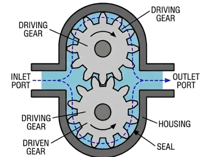
The mechanical pumping action is identical — rotating gears trap and displace fluid. What changes in a hydraulic gear pump is the operating environment and what the pump is asked to do with that fluid.
In a standard fluid transfer application, a gear pump moves fluid from point A to point B — the output is flow, measured in litres per minute (LPM). In a hydraulic system, the pump's job is to convert mechanical energy (from a motor or engine) into hydraulic power — a combination of flow and pressure that downstream actuators (cylinders, hydraulic motors) can use to do mechanical work.
This distinction has real engineering consequences:
Hydraulic power is the product of pressure and flow. The gear pump is responsible for producing the flow — pressure is a result of resistance in the system (loads on actuators, restrictions in the circuit). Understanding this distinction is fundamental to hydraulic system design.
Key principle: A gear pump does not create pressure. It creates flow. Pressure is generated when that flow meets resistance. If a hydraulic pump is running into an open tank with no load, it produces maximum flow at near-zero pressure.
The hydraulic power formula:
Hydraulic Power (kW) = Pressure (bar) × Flow Rate (LPM) ÷ 600
For example, a gear pump delivering 40 LPM at 200 bar is generating 40 × 200 ÷ 600 = 13.3 kW of hydraulic power. The motor driving that pump must supply at least this much mechanical power (plus losses for pump inefficiency — typically 10–20% more).
A hydraulic gear pump's output is defined primarily by its geometric displacement — the volume of fluid moved per revolution, expressed in cc/rev (cubic centimetres per revolution) or mL/rev.
Theoretical Flow (LPM) = Displacement (cc/rev) × Speed (RPM) ÷ 1000
A pump with a displacement of 11 cc/rev running at 1450 RPM delivers a theoretical output of 11 × 1450 ÷ 1000 = 15.95 LPM. Actual output will be slightly less, reduced by volumetric efficiency (typically 85–95% for a gear pump in good condition).
Unlike piston pumps, gear pumps have fixed displacement — the volume per revolution cannot be adjusted in the field. To change flow output, you change either the pump model or the drive speed.
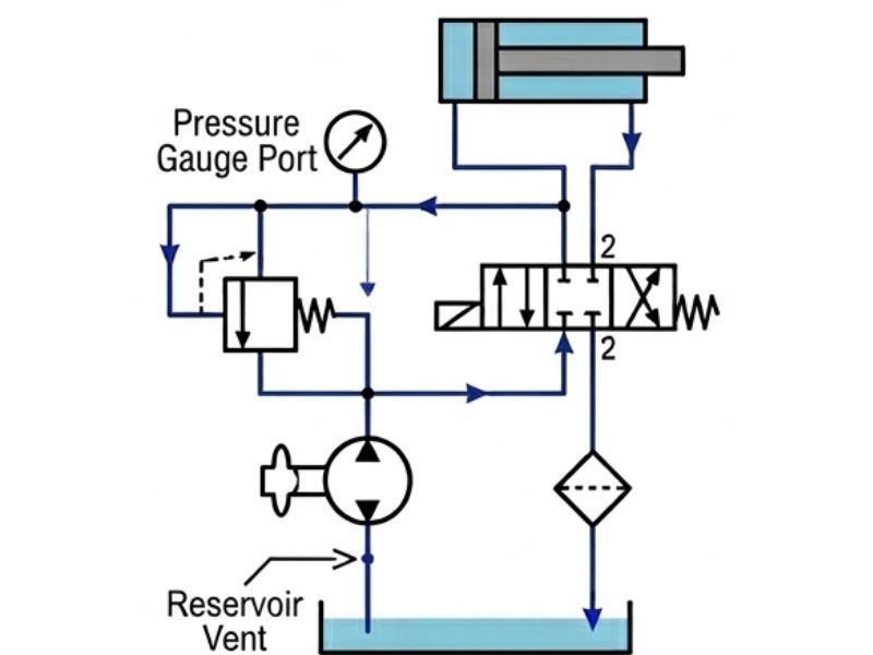
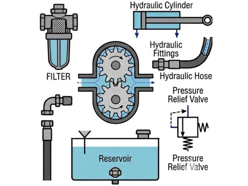
Most industrial and mobile hydraulic systems use an open-centre or open-loop circuit. The gear pump draws fluid from a reservoir, pressurises it, and delivers it to the control valve and actuators. After work is done, fluid returns to the reservoir where it cools and settles before being drawn again.
Step-by-Step Flow Through an Open Hydraulic Circuit
Important: When the relief valve is open and flow is circulating back to the reservoir without doing useful work, the full pump output is being converted to heat. Sustained relief valve operation is a common cause of hydraulic fluid overheating and premature component failure.
In a hydraulic gear pump, the fluid serves three simultaneous functions — and each one affects how the pump must be selected, maintained, and operated.
Fluid is the medium through which force is transmitted through the system. Hydraulic gear pumps are designed around the incompressibility of hydraulic fluid — a property that allows pressure to be transmitted near-instantaneously from pump to actuator. Any air or vapour in the fluid is compressible and disrupts this transmission, causing spongy, unpredictable actuator response.
Unlike many pump types that have separate lubrication systems, hydraulic gear pumps are lubricated entirely by the hydraulic fluid passing through them. The fluid film between rotating gears, between gears and side plates, and on bearing surfaces is what prevents metal-to-metal contact.
This is why fluid viscosity is a critical selection parameter for hydraulic gear pumps:
Most hydraulic gear pumps are rated for ISO VG 32, VG 46, or VG 68 hydraulic oil — the exact grade depending on operating temperature and system pressure.
Mechanical losses in the pump (friction, internal leakage) convert energy to heat, which is absorbed by the hydraulic fluid. If the hydraulic system has an adequate reservoir volume and (where required) an oil cooler, this heat is dissipated safely. If the system runs too hot — typically above 60°C continuous — fluid viscosity drops, internal leakage increases, seals degrade, and fluid oxidises. Fluid condition monitoring (viscosity, acid number, particle count) is the primary maintenance indicator for hydraulic gear pump systems.
Read More: Gear Pump Troubleshooting Guide
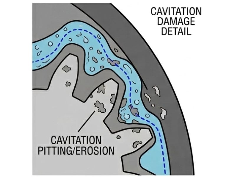
Cavitation is one of the most destructive phenomena in hydraulic gear pump operation, and it is almost entirely preventable with proper system design.
Cavitation occurs when the fluid pressure at the pump inlet drops below the vapour pressure of the hydraulic fluid. At this point, dissolved gases and vapour bubbles form in the fluid. When these bubbles are carried into the high-pressure discharge side of the pump, they collapse violently — generating localised pressure spikes that erode metal surfaces on gear teeth, the pump body, and side plates.
External hydraulic gear pumps — particularly those used at higher pressures — often have a third port beyond the suction and discharge: the case drain port.
Inside any gear pump, a small amount of fluid leaks from the high-pressure discharge side back to the low-pressure areas — this is normal and is what lubricates the internal components. In high-pressure hydraulic applications, this internal leakage pressurises the pump casing (the space around the gears and bearings). If casing pressure is not relieved, it stresses the shaft seal, leading to premature seal failure and external leakage.
The case drain line carries this low-pressure internal leakage from the pump casing directly back to the reservoir (not into the return line, which may itself be under back-pressure). This maintains near-zero pressure inside the casing and protects the shaft seal.
Critical installation note: The case drain line must always return fluid to the reservoir above the oil level — never into the return line. If the drain line is connected to a pressurised return line, casing pressure rises and accelerates shaft seal failure. The drain line should also be the last line disconnected when removing the pump, and the first connected when reinstalling, to prevent the casing running dry.
Selecting a hydraulic gear pump for a specific application requires matching the pump's capabilities to the system's demands. The following parameters define the selection:
| Parameter | What It Defines | Typical Gear Pump Range |
|---|---|---|
| Displacement (cc/rev) | Volume moved per shaft revolution — determines flow at a given RPM | 1 – 200 cc/rev |
| Maximum Continuous Pressure (bar) | Highest pressure the pump can sustain indefinitely | 150 – 250 bar |
| Maximum Peak Pressure (bar) | Short-duration maximum (e.g., cylinder end-of-stroke) | Up to 350 bar |
| Speed Range (RPM) | Min and max allowable shaft speed | 500 – 3500 RPM |
| Volumetric Efficiency (%) | Actual flow vs. theoretical flow — indicates internal leakage | 85 – 95% |
| Overall Efficiency (%) | Hydraulic power out vs. mechanical power in | 75 – 90% |
| Inlet Vacuum Limit (bar abs) | Maximum allowable suction vacuum without cavitation risk | 0.7 – 0.8 bar abs |
| Case Pressure Limit (bar) | Maximum allowable back-pressure on the case drain port | 0.5 – 3 bar |
A hydraulic press requires a cylinder to extend with 50 kN of force at a speed of 50 mm/s. The cylinder bore is 100 mm (area = 78.5 cm²).
In practice, a 16–18 cc/rev pump at 1450 RPM would be a starting point, with final selection cross-checked against the pump manufacturer's performance curves.
Hydraulic gear pumps are sensitive to both the type and cleanliness of the hydraulic fluid. Using an incompatible fluid or operating with contaminated fluid are the two leading causes of premature pump failure.
Hydraulic system contamination is the cause of the majority of hydraulic component failures. Gear pumps, with their tighter clearances than vane or piston pumps in some configurations, are particularly sensitive to solid particle contamination.
The ISO 4406 cleanliness standard defines allowable particle counts at three size thresholds (4μm, 6μm, 14μm). For a hydraulic gear pump:
| Symptom | Likely Cause | Corrective Action |
|---|---|---|
| No flow or low flow at startup | Air in suction line or pump not primed | Check suction connections, prime pump, inspect for air entry points |
| Noisy operation (whine/squeal) | Cavitation — restricted inlet | Service suction strainer, check line size and routing |
| Noisy operation (knock/rattle) | Aeration — air entering through suction fittings | Check and tighten all suction fittings; inspect reservoir for foam |
| High fluid temperature | Relief valve bypassing continuously, excessive internal leakage | Check system load vs. relief setting; test volumetric efficiency |
| Shaft seal leaking | Excessive case pressure or worn seal | Check case drain routing; replace seal and investigate root cause |
| Flow gradually declining over time | Increasing internal wear — reducing volumetric efficiency | Test pump output at rated pressure; rebuild or replace if efficiency <80%< /td> |
| Pump seizing / locked rotor | Cavitation damage, thermal expansion, contamination | Replace pump; identify and fix root cause before reinstalling |
Gear pumps are among the more robust hydraulic components, but sustained performance depends on a proactive maintenance regime focused on the hydraulic fluid and inlet conditions — not primarily the pump itself.
Selecting a hydraulic gear pump involves matching displacement, pressure rating, speed, fluid compatibility, and mounting configuration to your specific circuit requirements. Getting this right at the specification stage avoids the most common causes of early pump failure — overspeeding, inlet starvation, fluid incompatibility, and operating beyond pressure ratings.
Unique Pump Systems manufactures hydraulic gear pumps engineered for Indian industrial conditions — with a wide range of displacements, materials, and configurations. To discuss your hydraulic system requirements or get a selection recommendation, explore the gear pump range or contact our application engineering team directly.
A hydraulic gear pump converts mechanical energy into hydraulic power by generating flow against system resistance. Its gear-based positive displacement mechanism produces fixed displacement per revolution, making output flow predictable and proportional to shaft speed. In hydraulic systems, the pump operates within a circuit that includes a reservoir, control valves, actuators, filters, and protective relief valves — each component interdependent with the pump's performance.
The key factors that separate a hydraulic gear pump from general fluid transfer gear pumps are its pressure ratings, displacement specifications, fluid viscosity requirements, cavitation sensitivity, and the potential need for a case drain line. Monitoring fluid condition, inlet restriction, and operating temperature are the three most important maintenance practices for ensuring hydraulic gear pump longevity.