Unique Pump Systems, Kailash Industrial Complex, Vikhroli (W)
Measuring a mechanical seal correctly is the most important step in identifying a replacement — and the step most often done incompletely. An incorrect shaft bore measurement leads to a seal that leaks from installation. A missed stuffing box depth measurement leads to a seal that bottoms out before the faces can close. A wrongly measured spring free length leads to incorrect face loading and premature failure within weeks. This guide covers all eight critical dimensions of a mechanical seal, the correct tool and technique for each, the tolerances that determine whether an existing shaft and housing are still within specification, the DIN EN 12756 standard reference dimensions for Type 41 and Type 42 seals, and a complete seal datasheet template for submitting an accurate replacement order. Whether you are measuring a seal from a running pump, identifying a seal from a worn sample, or specifying a new seal installation, this guide gives you everything you need to get the measurement right first time.
Also Read: Types of Mechanical Seals | How to Replace a Mechanical Seal
Accurate seal measurement requires precision measuring instruments. Using a steel rule or tape measure for any seal dimension — even shaft diameter — will produce errors large enough to order the wrong seal. The following instruments are required:
| Tool | Specification Required | What It Is Used For | Accuracy |
|---|---|---|---|
| Vernier calliper or digital calliper | 150 mm or 200 mm jaw capacity; resolution 0.02 mm or better | Shaft bore ID, seat OD, seat thickness, stuffing box bore and depth, seal face OD | +/- 0.02 mm |
| Outside micrometer | Range covering shaft diameter (e.g., 25–50 mm for a 40 mm shaft); resolution 0.01 mm | Precise shaft diameter confirmation; spring wire diameter | +/- 0.01 mm |
| Inside micrometer or bore gauge | Range matching stuffing box bore diameter; resolution 0.01 mm | Stuffing box bore internal diameter (more accurate than calliper for deep bores) | +/- 0.01 mm |
| Dial test indicator (DTI) with magnetic stand | 0.001 mm graduation; 5–10 mm travel; carbide contact point | Shaft runout measurement; face flatness check on shaft sleeve | +/- 0.002 mm |
| Steel rule or depth gauge | 150 mm; 0.5 mm graduation acceptable | Stuffing box depth; spring free length (preliminary check) | +/- 0.5 mm |
| Optical flat (optional) | Grade 2 minimum; 60–80 mm diameter for standard seal faces | Seal face flatness verification using monochromatic light (sodium lamp) | Flatness to 3 light bands (approx. 0.9 micron) |
| Engineer's square (if optical flat unavailable) | 75 mm or 100 mm; Grade 1 | Checking face flatness by checking for rocking on a surface plate | Qualitative check only |
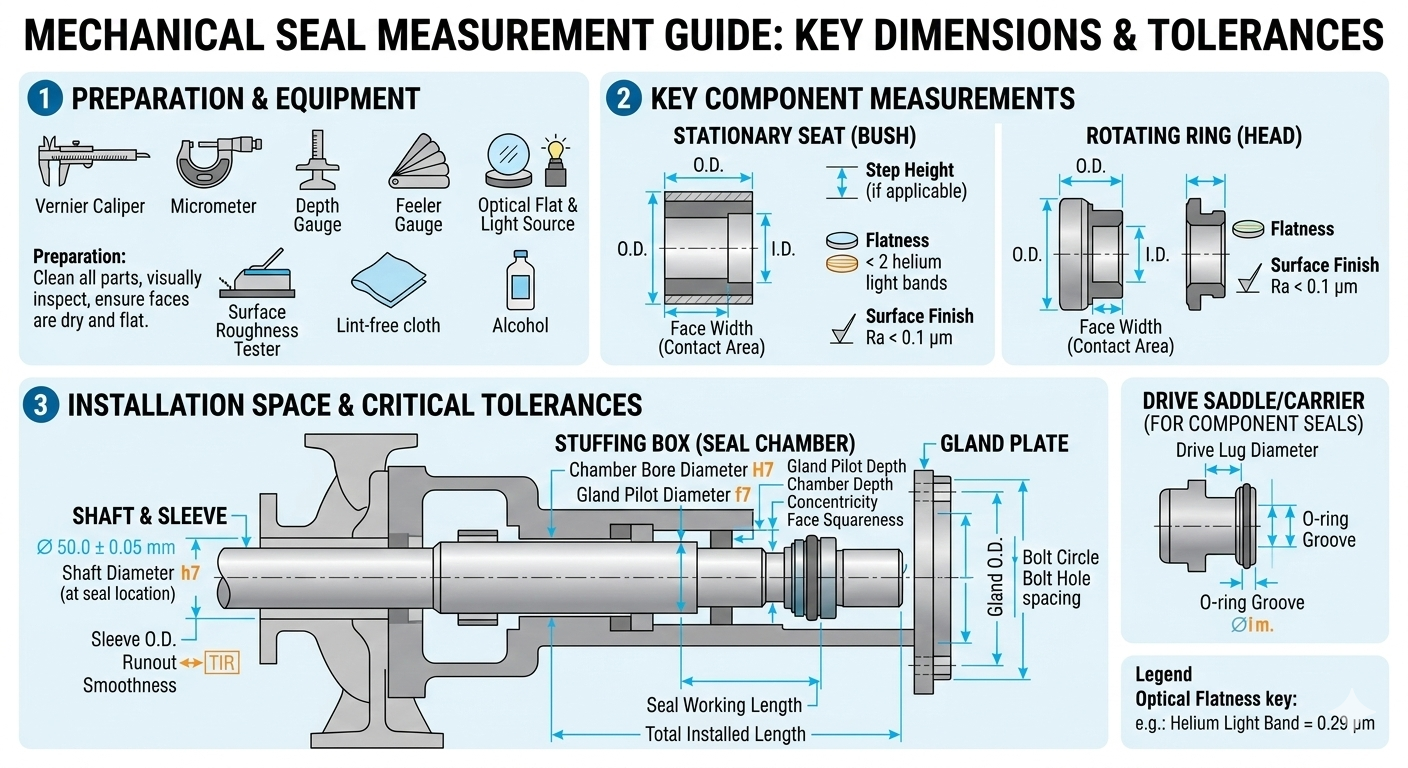
A complete mechanical seal specification requires eight measurements. Every one is needed — providing only shaft diameter and seal type is not enough to guarantee the correct replacement, particularly for non-standard or older pump models.
| Dimension | Symbol | What It Defines | Primary Use |
|---|---|---|---|
| Shaft bore diameter (seal bore ID) | d1 | The inside diameter of the rotating seal ring — must match the shaft or sleeve diameter | Determines the seal size designation per DIN EN 12756 |
| Seat outside diameter | D | The outer diameter of the stationary seat | Determines whether the seat fits in the stuffing box bore |
| Seat thickness | L1 | The axial depth of the stationary seat | Determines how much of the stuffing box depth the seat occupies |
| Spring free length | Lf | The uncompressed length of the spring(s) | Verifies spring is not fatigued; confirms seal model identity |
| Seal installed working length | L | The total axial length of the complete assembled seal from shaft shoulder or sleeve face to gland plate face | Most critical dimension — determines correct face closing force |
| Stuffing box bore diameter | D2 | The internal bore diameter of the pump stuffing box or seal chamber | Determines maximum seat OD that will fit; confirms seal chamber is correct for the seal |
| Stuffing box depth | L2 | The axial depth from the stuffing box face to the shaft shoulder or back of chamber | Determines the available installation space; must match seal working length |
| Shaft runout (TIR) | TIR | The total indicator reading of shaft lateral movement at the seal installation position | Determines whether shaft is within tolerance for the seal to work — not a seal dimension but equally critical |
The shaft bore diameter is the single dimension that defines the seal's size designation per DIN EN 12756 and most other international standards. Every other dimension follows from this. Getting it right is the most important measurement you will take.
Measure the inside diameter of the rotating seal ring (also called the seal head, rotating face assembly, or primary ring) at the bore — the hole through which the shaft passes. On a Type 41 seal, this is the bore through which the O-ring seats against the shaft. On a Type 42, this is the bore through which the V-packing ring contacts the shaft.
Do not measure the shaft itself as a substitute for the seal bore — a new seal's bore is machined to fit a shaft of the nominal size, but there is always a small clearance fit. Measuring the shaft gives the shaft size; measuring the seal bore gives the seal size. In most standard designs these are nominally the same number (a '25 mm seal' fits a 25 mm shaft), but if the seal has been used on a stepped sleeve or undersized shaft, the shaft diameter and the seal bore may differ.
DIN EN 12756 defines standard shaft diameter sizes for Type 41 and Type 42 seals. The bore of a new seal is machined to a tight tolerance fit on the shaft. Standard nominal shaft sizes covered by DIN EN 12756:
| DIN Nominal Shaft Size (mm) | Seal Bore ID (d1) — Nominal | Typical Bore Tolerance (new seal) | Acceptable Shaft Diameter Range |
|---|---|---|---|
| 10 mm | 10.0 mm | +0.0 / +0.1 mm | 9.95 – 10.00 mm |
| 12 mm | 12.0 mm | +0.0 / +0.1 mm | 11.95 – 12.00 mm |
| 14 mm | 14.0 mm | +0.0 / +0.1 mm | 13.95 – 14.00 mm |
| 16 mm | 16.0 mm | +0.0 / +0.1 mm | 15.95 – 16.00 mm |
| 18 mm | 18.0 mm | +0.0 / +0.1 mm | 17.95 – 18.00 mm |
| 20 mm | 20.0 mm | +0.0 / +0.1 mm | 19.95 – 20.00 mm |
| 22 mm | 22.0 mm | +0.0 / +0.1 mm | 21.95 – 22.00 mm |
| 24 mm | 24.0 mm | +0.0 / +0.1 mm | 23.95 – 24.00 mm |
| 25 mm | 25.0 mm | +0.0 / +0.1 mm | 24.95 – 25.00 mm |
| 28 mm | 28.0 mm | +0.0 / +0.1 mm | 27.95 – 28.00 mm |
| 30 mm | 30.0 mm | +0.0 / +0.1 mm | 29.95 – 30.00 mm |
| 33 mm | 33.0 mm | +0.0 / +0.1 mm | 32.95 – 33.00 mm |
| 35 mm | 35.0 mm | +0.0 / +0.1 mm | 34.95 – 35.00 mm |
| 38 mm | 38.0 mm | +0.0 / +0.1 mm | 37.95 – 38.00 mm |
| 40 mm | 40.0 mm | +0.0 / +0.1 mm | 39.95 – 40.00 mm |
| 43 mm | 43.0 mm | +0.0 / +0.1 mm | 42.95 – 43.00 mm |
| 45 mm | 45.0 mm | +0.0 / +0.1 mm | 44.95 – 45.00 mm |
| 48 mm | 48.0 mm | +0.0 / +0.1 mm | 47.95 – 48.00 mm |
| 50 mm | 50.0 mm | +0.0 / +0.1 mm | 49.95 – 50.00 mm |
| 55 mm | 55.0 mm | +0.0 / +0.1 mm | 54.95 – 55.00 mm |
| 60 mm | 60.0 mm | +0.0 / +0.1 mm | 59.95 – 60.00 mm |
The stationary seat (also called the seat insert, stationary face, or mating ring) sits in the stuffing box bore and must fit correctly — too loose and it will rotate with the shaft instead of remaining stationary; too tight and it cannot be pressed in without cracking.
Measure the maximum outside diameter of the stationary seat disc — across its flat circular face, not at any chamfer or relief groove around the periphery. If the seat has an O-ring groove around its outer circumference, measure the land diameter outside the groove (the full diameter of the seat body), not the groove depth.
The seat OD must be slightly smaller than the stuffing box bore for O-ring-mounted seats, or slightly larger (interference fit) for press-fit seats in a cup mounting. Typical fits:
The seat thickness is the axial dimension of the stationary seat — how far it protrudes into the stuffing box. This dimension, combined with the stuffing box depth, determines how much space remains for the rotating seal assembly.
The spring (or springs in a multi-spring design) provides the closing force that keeps the seal faces in contact throughout the seal's operating life. The free length — the length of the spring when completely unloaded — is a primary indicator of spring fatigue and confirms the seal model identity.
The spring free length is used to verify that the spring has not fatigued in service. A fatigued spring is shorter than the original specification — this reduces the installed closing force, leading to inadequate face contact, fluid film instability, and leakage. Compare the measured free length against the manufacturer's specification for the seal model. A reduction of more than 10% from the nominal free length indicates the spring should be replaced even if visually intact.
The installed working length — sometimes called the installation dimension, assembly length, or seal length — is the total axial dimension of the complete rotating seal assembly as installed on the shaft. It is measured from the shaft shoulder (or sleeve end face) to the back face of the gland plate when the seal is correctly installed with the specified spring compression.
This is the most frequently misunderstood measurement in mechanical seal specification, and errors here cause more installation failures than any other single dimension mistake.
A mechanical seal works because the spring is compressed by a specific amount during installation — the difference between the spring's free length and its installed (compressed) length. This compression creates the spring closing force that keeps the faces in contact. The spring compression is set by positioning the drive collar set screws at the correct position on the shaft.
If the working length is set too long (drive collar too far from the gland plate), the spring is insufficiently compressed — face contact pressure is too low, the fluid film becomes unstable, and the seal leaks. If the working length is set too short, the spring is over-compressed — the faces overheat from excessive contact pressure, the elastomers distort, and the seal fails prematurely.
The stuffing box (also called the seal chamber) is the recess in the pump casing into which the mechanical seal is installed. Its bore diameter determines the maximum seat OD that can be fitted, and its surface condition affects O-ring seating and seal positioning.
The stuffing box depth is the axial distance from the front face of the stuffing box (where the gland plate seals) to the shaft shoulder or bottom of the seal chamber at the back. This dimension determines whether the selected seal's working length will fit within the available space.
For the seal to function correctly, the stuffing box depth (L2) must accommodate: the seat thickness (L1) plus the seal working length (L) plus a minimum clearance of 1–2 mm. The relationship is:
If L2 is less than the sum of L1 + L, the seal cannot be installed with the correct spring compression — the gland plate will bottom out on the stuffing box face before the drive collar reaches its correct position on the shaft. In this situation, either a shorter seal assembly is required, or the stuffing box must be machined deeper.
Shaft runout is not a dimension of the seal itself — it is a measurement of the pump shaft's lateral movement at the position where the seal is installed. It is, however, as critical as any seal dimension for determining whether the seal will work. More mechanical seals fail due to excessive shaft runout than from any measurement error in the seal's own dimensions.
As the shaft rotates, any eccentricity (wobble) causes the rotating seal face to move laterally relative to the stationary seat. The seal faces must follow this lateral movement while maintaining contact — they do this by rocking slightly on each revolution. Beyond a critical runout value, the faces cannot follow the shaft movement, the fluid film breaks down, and the seal leaks.
Additionally, shaft runout causes the O-ring or secondary seal to slide back and forth on the shaft sleeve on every revolution — this is the 'fretting' wear mechanism that eventually creates a groove in the shaft sleeve at the O-ring position.
| Shaft Diameter (mm) | Maximum Acceptable Runout (TIR) | Action if Exceeded |
|---|---|---|
| Up to 25 mm | 0.05 mm (50 microns) | Check bearing condition and preload; check shaft for bend; replace shaft if bent |
| 25 – 50 mm | 0.05 mm (50 microns) | Check bearing condition and preload; check shaft for bend; replace shaft if bent |
| 50 – 75 mm | 0.06 mm (60 microns) | Check bearing condition; align coupling; check for bent shaft |
| 75 – 100 mm | 0.08 mm (80 microns) | Check bearing housing alignment; coupling alignment; worn bearing housing |
| Over 100 mm | 0.10 mm (100 microns) | Full alignment check; bearing replacement; possible shaft bow survey |
In many cases — particularly in older plants where seal records are incomplete — the task is to identify a replacement from a worn or partially damaged seal removed from the pump. The following procedure works even with a seal in poor condition:
The material combination of the rotating face and stationary seat is as important as the dimensional measurements for ordering a correct replacement. Material identification from a removed seal:
| Material | Visual Appearance | Physical Test | Typical Use |
|---|---|---|---|
| Carbon-graphite (rotating face) | Dull black; slightly grainy texture; lighter areas on worn face track | Scratches easily with a steel tool; leaves black mark like pencil on paper | Standard rotating face for most water, chemical, and oil service seals |
| Ceramic (Al2O3) (seat) | Opaque white or light grey; hard polished face; may have slight pink tint (95% alumina) | Does not scratch with steel tool; brittle — will crack if dropped; very smooth face | Standard seat for water and mild chemical service; low cost |
| Silicon carbide (SiC) (face or seat) | Grey to dark grey; slightly metallic sheen; very smooth, mirror-like polished face | Does not scratch with steel; harder than ceramic; emits faint metallic ring when tapped gently | Chemical, abrasive, and high-pressure service; both face and seat may be SiC |
| Tungsten carbide (TC) (face or seat) | Dark grey to silver-grey; very heavy for its size (density 15 g/cm³ vs SiC 3.2 g/cm³) | Much heavier than ceramic or SiC of same size; does not scratch with steel; slight metallic appearance | Highly abrasive and high-pressure service; often used in pairs or against carbon |
| Stainless steel (metal parts) | Bright silver; non-magnetic (SS316) or slightly magnetic (SS304) | Resists scratching; non-magnetic test for SS316 | Drive collar, spring, gland plate, seat holder |
| Measurement Mistake | What Goes Wrong | Resulting Seal Failure Mode |
|---|---|---|
| Measuring shaft diameter instead of seal bore ID | Shaft may be undersized, worn, or on a sleeve — gives wrong bore value | Seal bore too loose on shaft; O-ring cannot seal; leakage from day 1 |
| Measuring only one diameter of the seat (not checking roundness) | Damaged or oval seat is ordered as a replacement; or worn seat is reused | Rocking seat — cannot form stable fluid film; leaks within days |
| Not measuring stuffing box depth | Selected seal working length does not fit available space | Gland plate bottoms out; spring over-compressed or faces cannot close; immediate failure |
| Not measuring shaft runout before ordering seal | New seal installed on bent shaft or with worn bearings | Rapid seal failure (days to weeks); wrongly blamed on incorrect seal supply |
| Reading spring free length without measuring wire diameter | Similar-looking spring with different load rating is ordered | Incorrect face closing force — either face opening or overheating |
| Using vernier calliper tilted in the bore (not perpendicular) | Reads larger than true ID — orders the next size up seal | Seal bore too large for shaft; O-ring cannot compress correctly; leakage |
| Not checking stuffing box bore for out-of-round or damage | New seal O-ring sits in a pitted or scored bore | Leak path around seat O-ring; seal appears to fail but pump leaks around the seal, not through it |
| Measuring a worn shaft diameter without noting sleeve undersize | Shaft has been ground down; seal bore ordered to worn dimension | Correct seal for worn shaft; but when shaft is reconditioned, seal is wrong size |
Use this template when ordering a replacement seal or submitting a measurement to a seal supplier. All fields are required for an accurate supply:
| Field | Your Measurement | Notes |
|---|---|---|
| Pump make and model | _______________ | If known — allows cross-reference to pump manufacturer's seal specification |
| Pump serial number | _______________ | Helps identify seal model from pump manufacturer records |
| Shaft diameter (measured at seal position) | ___ mm | Measure with outside micrometer; record to 0.01 mm |
| Shaft bore ID of removed seal (d1) | ___ mm | Primary size designation; record to 0.02 mm |
| Seat outside diameter (D) | ___ mm | Record to 0.02 mm; note if O-ring mounted or cup mounted |
| Seat thickness (L1) | ___ mm | Record to 0.05 mm |
| Spring free length (Lf) | ___ mm | Record to 0.5 mm |
| Spring wire diameter | ___ mm | Record to 0.1 mm; measure with micrometer |
| Number of springs | ___ | 1 for single coil spring; 6/8/12 for multi-spring designs |
| Seal installed working length (L) | ___ mm | Measured from shaft shoulder to gland plate face |
| Stuffing box bore diameter (D2) | ___ mm | Record to 0.05 mm; note surface condition |
| Stuffing box depth (L2) | ___ mm | Record to 0.5 mm |
| Shaft runout (TIR) | ___ mm | Must be within acceptable limit before fitting new seal |
| Rotating face material | _______________ | Carbon / SiC / TC / other — identify from visual/physical test above |
| Seat material | _______________ | Ceramic / SiC / TC / other |
| O-ring / secondary seal material | _______________ | NBR / Viton / EPDM / PTFE — identify from visual/physical test above |
| Spring and metal part material | _______________ | SS316 / SS304 / Hastelloy / other |
| Seal rotation direction | CW / CCW / Unknown | As viewed from drive end; critical for single coil spring seals (Type 41) |
| Fluid being sealed | _______________ | Process fluid type, concentration, and temperature |
| Operating pressure (bar) | ___ bar | Discharge pressure at the seal face |
| Operating temperature (°C) | ___ °C | Fluid temperature at the seal |
| Shaft speed (RPM) | ___ RPM | From motor nameplate or pump datasheet |
| Photographs attached? | Yes / No | Strongly recommended — attach clear photos of rotating assembly, seat (both faces), and any markings |
Many pumps use a shaft sleeve — a replaceable cylindrical liner that fits over the pump shaft in the seal region. The mechanical seal fits over the sleeve, not directly over the shaft. This is important because the sleeve OD is the effective 'shaft diameter' for seal selection, and it may differ from the pump's shaft diameter.
Unique Pump Systems supplies mechanical seals in Type 41 (O-ring type) and Type 42 (V-packing type) configurations to DIN EN 12756 standard, covering shaft diameters from 10 mm to 100 mm with face materials in carbon, silicon carbide, and tungsten carbide. To ensure you receive the correct replacement seal, use the measurement datasheet above and submit all measurements when placing an enquiry. For worn or unidentified seals where cross-referencing is uncertain, our technical team can assist in identifying the correct replacement from your measurements and photographs.
To correctly specify a mechanical seal replacement, take all eight measurements in this sequence:
Complete all measurements, fill in the datasheet, identify face and elastomer materials, and submit with photographs. A complete submission guarantees the correct replacement is supplied first time — avoiding the cost of a second removal, a second seal, and another maintenance window.