Unique Pump System, Kailash Industrial Complex, Vikhroli West
We express our pleasure in welcoming you as a new addition to our customers family. The pumps you have just now acquired have been manufactured by UNIQUE PUMP SYSTEMS using the best technology and the standards.
This manual will provide you with all necessary technical data with detailed illustration to enable you to install the machine correctly to operate the machine properly for excellent results and to maintain it for longer period of trouble free performance.
A section of the manual is devoted specifically for trouble shooting and to correctly ordering the spare part, should it become necessary.
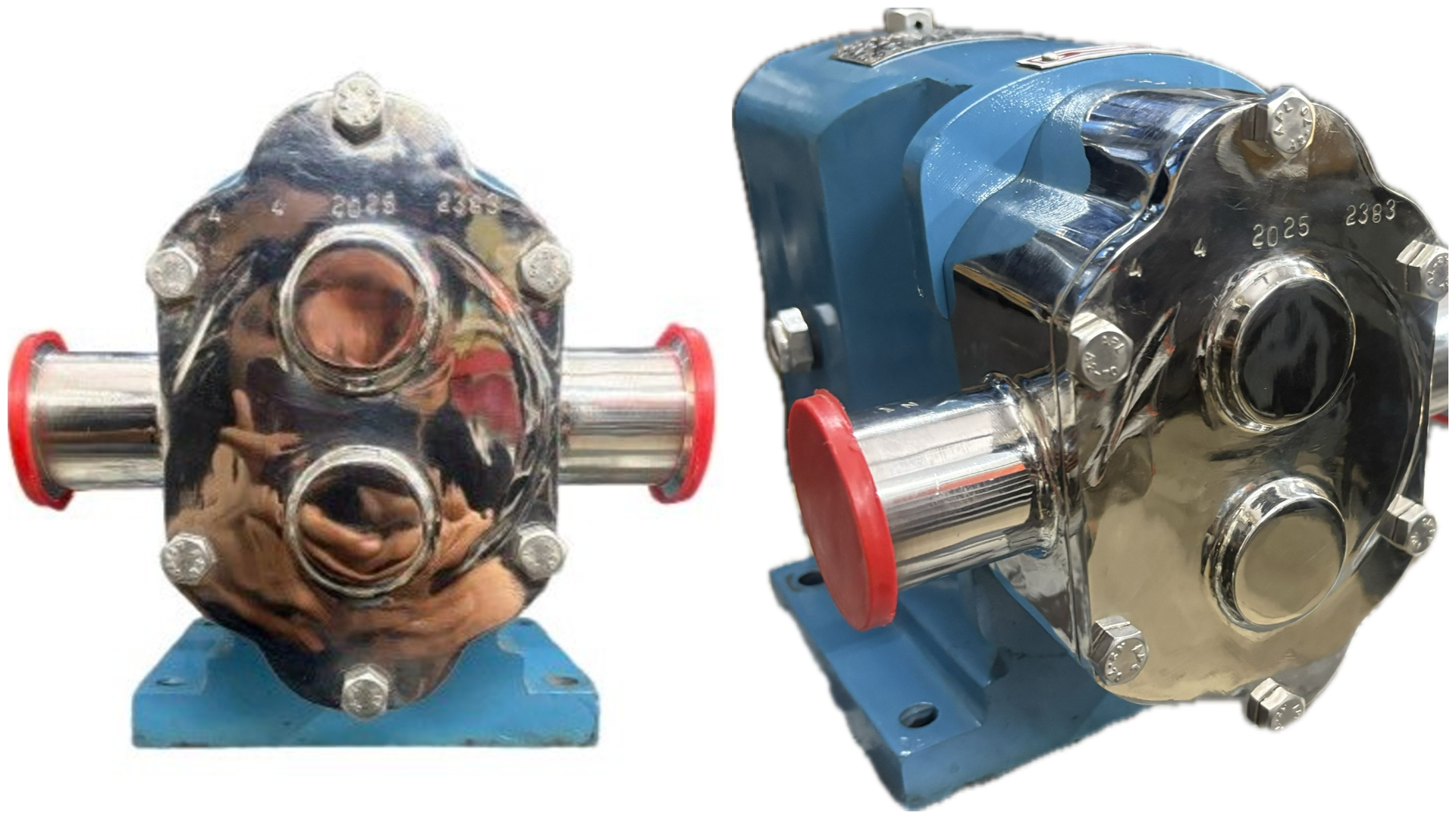
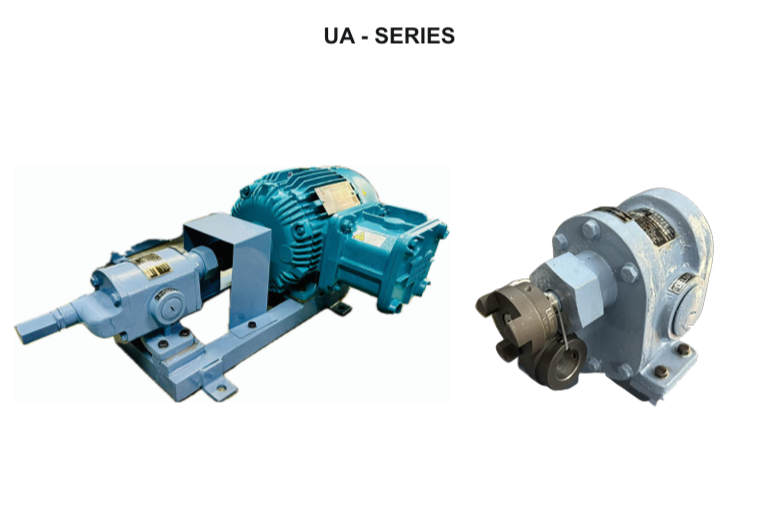
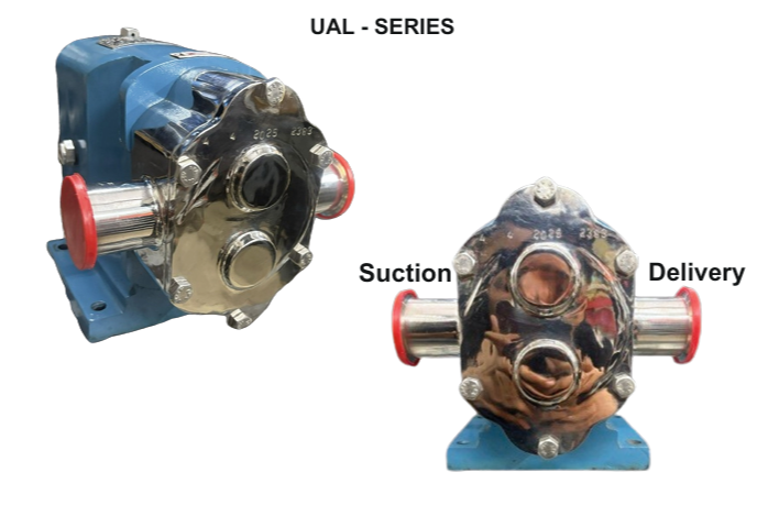
The S. S. LOBE PUMP is intended for the use in Dairies, Pharmaceutical, Beverages & Other Allied Industries constructed for the smooth operation and are totally hygienic. The S. S. LOBE PUMP is provided with a special soft seal suitable for handling Milk, Pharmaceutical & Food products. All the parts which are coming in contact withliquid are made of high alloy stainless steel. The S. S. LOBE PUMP of PP/LP type are non-priming pumps with Double Mechanical Shaft Seal.
ALWAYS LEVEL THE PUMP THROW BALL FEET. ENSURE THAT SUCTION AND DISCHARGE PIPES ARE TENSIONS FREE AND DO NOT LEAN ON THE PUMP.
After pump is taken out from packing case. It should be checked for any damage during transit. Remove S. S. Motor cover before lifting the pump while connecting the pipe lines to the pump ports, care should be taken by providing pipe supports suitable to avoid the weight of piping on the pump casing. Position the pump horizontally by adjusting the ball feet and ensure that the pump stands freely on all 4 legs. Tighten the clamping ring well before staring the pump.
Connect the motor to the supply as per specification given on the name plate. Check that Pump rotates in as per direction arrow.
Care should be taken to keep opening in the motor cover free from air circulation. The pump should be run at rated through put. If this is not observed, it may lead to permanent overload of the motor and break down. The through put at the rated head mentioned in the specification column can be adjusted by a throttle valve installed in the discharge line.
The motor current should not exceed the rated current indicated on the name plate of the motor.
ALWAYS CLEAN THE PIPE LINE BEFORE COMMISSIONING OF THE PUMP OTHERWISE THE DIRT/WELD PARTICLES SHALL DAMAGE THE MECHANICAL SHAFT SEAL OF THE PUMP.
Water jet should not be directed at the terminal box of motor. Shaft extension, shaft seal should be handled very carefully äs these parts are precise and delicate For dismantling the lobe extractor supplied with the pump.
| Sr. No. | REASON | REMEDY |
|---|---|---|
| 1 | Suction line is leaky | Seal the suction line. |
| 2 | Shaft seal defective. | Replace the shaft seal. |
| 3 | Seal ring is worn out. | Replace the seal ring. |
| 4 | Seal ring in suction or discharge ports are worn out. | Replace the seal ring. |
| 5 | Air is leaked inside the pump and mixed liquid to be pumped. | Prevent air to leak inside the pump. |
| 4 | Direction or rotation of pump is not correct | Change the direction of pump rotation. It should be as per direction arrow. |
| Sr. No. | Maintenance Parts | Quantity |
|---|---|---|
| 1 | Suction line is leaky | Open the valves |
| 2 | Shaft seal defective. | Clean the suction line. |
SIZE:_____ HP:_____ RPM:_____
DESIGN QUALIFICATIONNote: LOBE PUMP IN LET SHOULD BE WITH IN 1 TO 1 ½ METER FROM VESEL OR IF MORE DISTANCE, LIQUID MUST REACH UPTO LOBE PUMP BODY THEN START PUMP.
Lobe pumps are similar to external gear pumps in operation in that fluid flows around the interior of the casing. Unlike external gear pumps, however, the lobes do not make contact. Lobe contact is prevented by external timing gears located in the gearbox. Pump shaft support bearings are locatedin the gearbox, and since the bearings are out of the pumped liquid, pressure is limited by bearing location and shaft deflection.